Continuously variable ratio transmission

a technology of constant ratio and transmission, applied in the direction of dynamo-electric gear control, machine/engine, gearing, etc., can solve the problems of insufficient single planetary gear set cannot meet the efficiency and control gain desired from a cvt, etc., to achieve the effect of increasing the overall efficiency and reducing the overall efficiency of the mechanical transmission

Inactive Publication Date: 2006-10-03
LEE PAUL Z
View PDF4 Cites 48 Cited by
  • Summary
  • Abstract
  • Description
  • Claims
  • Application Information

AI Technical Summary

Benefits of technology

[0022]The above and other objects of the present invention are achieved by coupling an auxiliary variable load electric generator, or servogenerator, to the control axle of the CVT. The servogenerator will generate electrical power especially in conditions in which the control axle to which it is coupled is being rotated at higher speeds. As noted in the Background section, it is at these speeds that the overall efficiency of the mechanical transmission is lowest. The electrical power generated by the servogenerator is put to use in the system to thereby increase the overall efficiency to a higher level.
[0023]The invention further involves the option of using, for low-noise applications, resilient gear elements which do not mesh by means of gear teeth, but rather by frictional engagement. Such elements reliably operate to maintain the desired input axle and output axle speed, and control of the transmission ratio, while substantially reducing the noise generated in operation, as compared with a system employing the meshing of steel (or other hard metal) gear teeth.

Problems solved by technology

In addition to efficiency concerns when operating at the higher end of transmission ratios, certain applications for which a CVT might be considered have requirement for low noise and the like, for which gear sets operating with meshed gear teeth may not be suitable.
Further, applications may exist in which the efficiency and control gain desired from a CVT can not be adequately met by a single planetary gear set.

Method used


Image

  • Continuously variable ratio transmission
  • Continuously variable ratio transmission
  • Continuously variable ratio transmission

Examples


Embodiment Construction

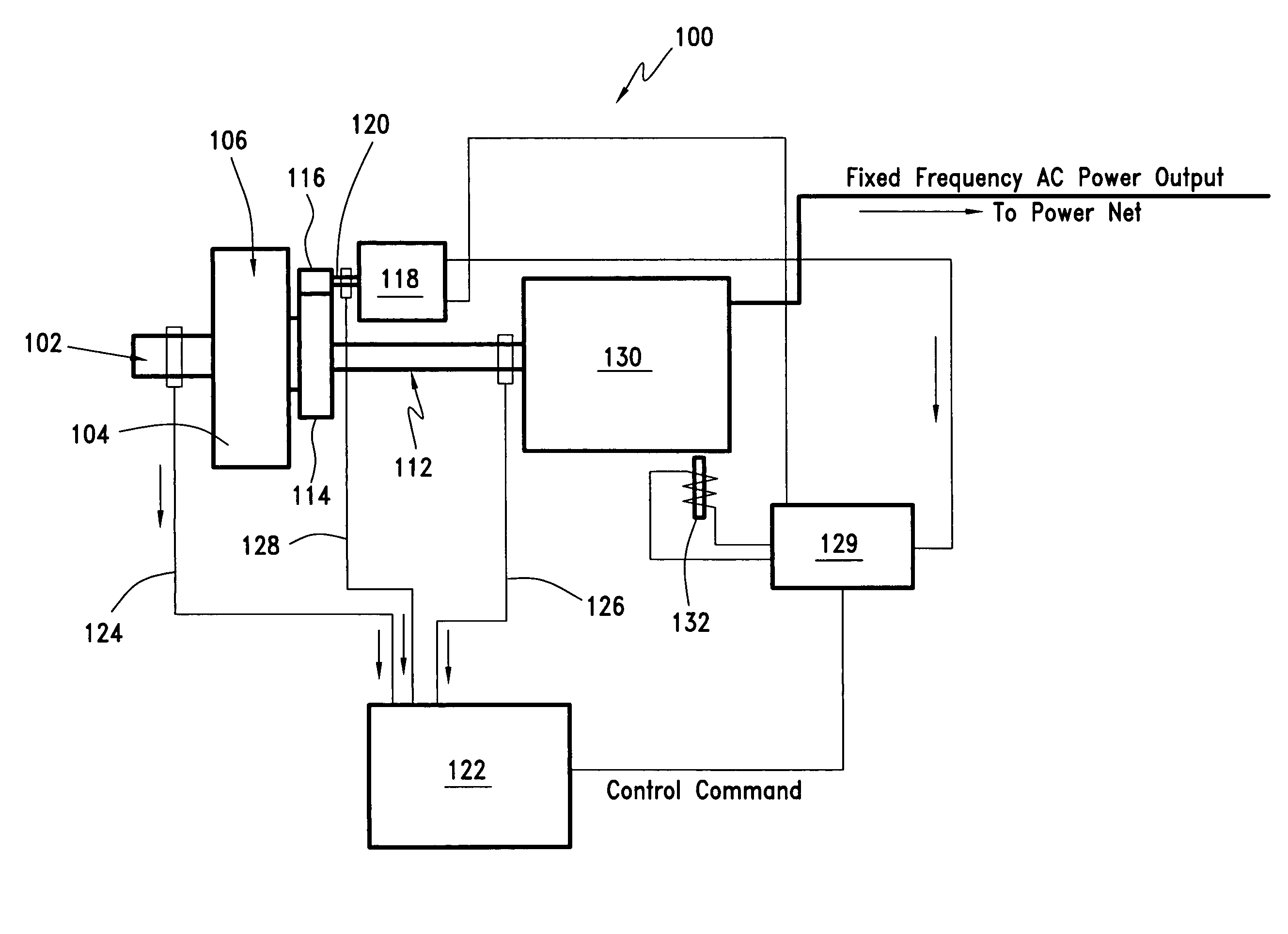
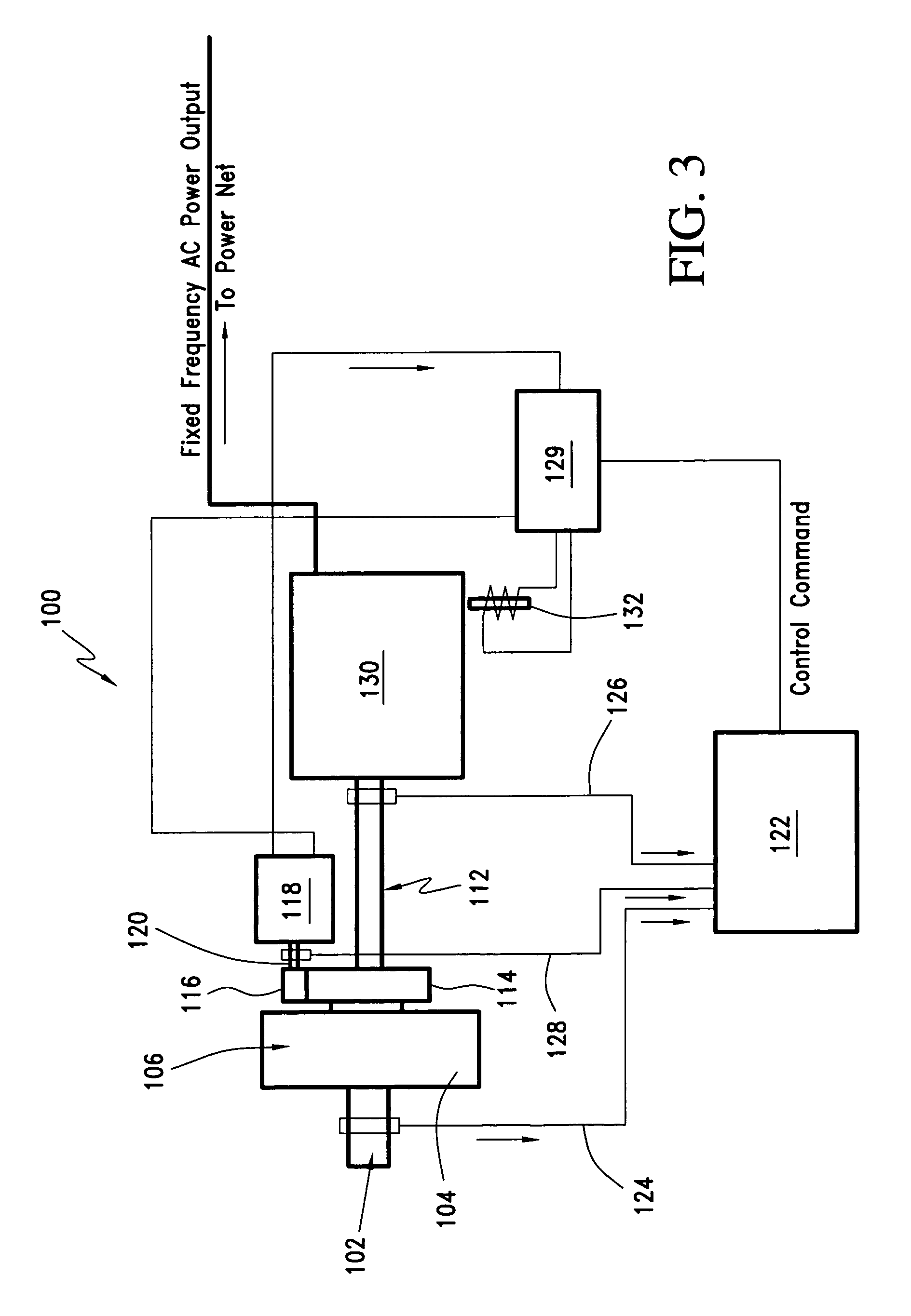
[0034]FIG. 3 illustrates, in schematic form, a continuously variable ratio transmission (CVT) system 100 in accordance with a preferred embodiment of the invention. In this embodiment (see also FIG. 4), a drive axle 102 connected to ring gear 104 provides the input to the system. Various preferred input sources will be described later in this specification.

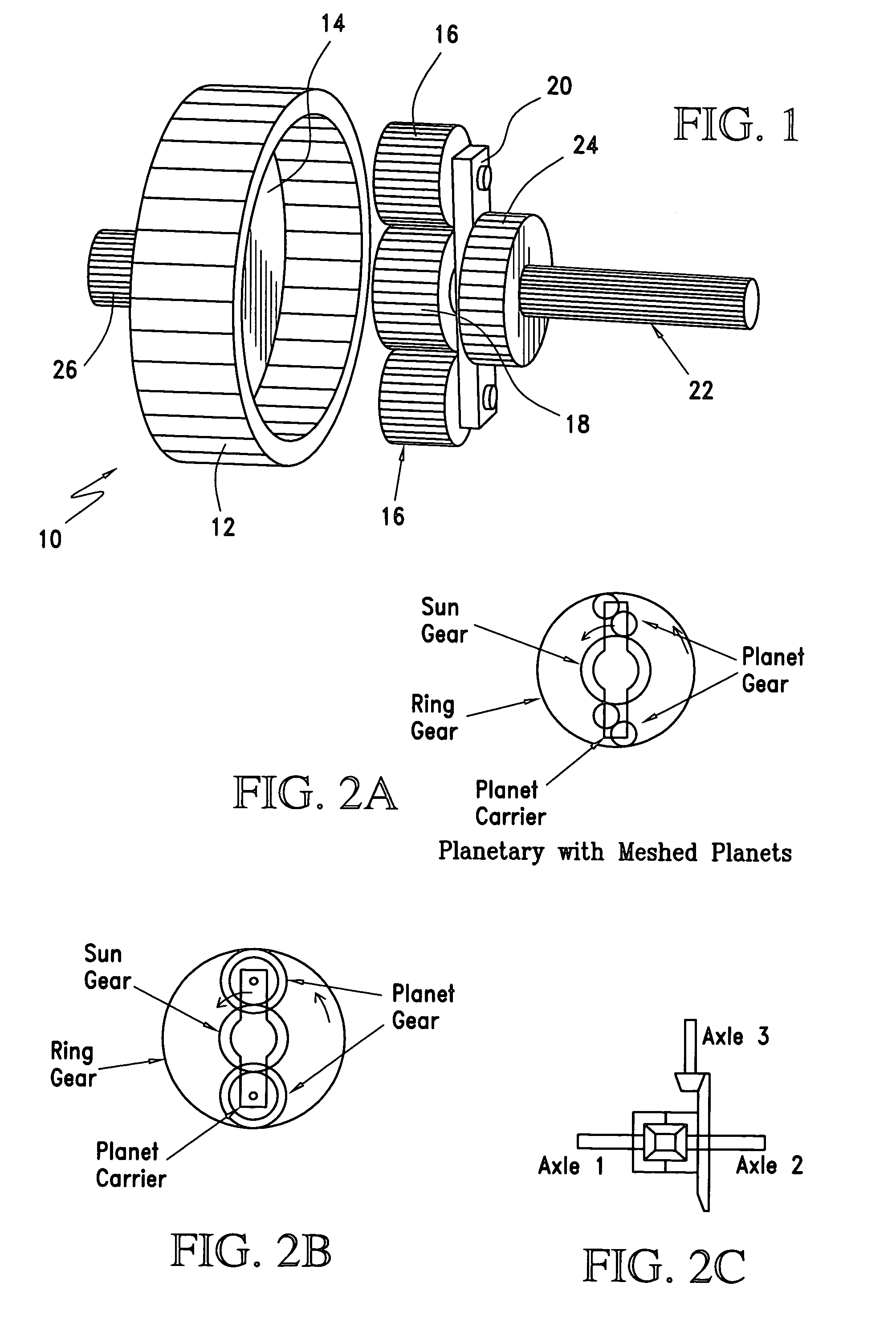
[0035]Ring gear 104 is coupled to sun gear 106 via planet gears 108 rotatingly attached to planet carrier 110. The view in FIG. 4 is an exploded view, and as will be well understood in the art, planet gears 108 and sun gear will, in operation, be housed within ring gear 104.

[0036]In the FIG. 3 embodiment, sun gear axle 112 is the output axle from the CVT. The transmission ratio between the drive or ring gear axle (input) 102 and sun gear axle (output) 112 is controlled by the planet gears and carrier 108, 110. More specifically, control of the ratio is effected by controlling the rate of rotation of planet carrier 110.

[0037]In the...


PUM


Abstract

A continuously variable ratio transmission including a planetary gear set having a sun gear, a ring gear, and a planet carrier having at least two planet gears carried thereon, a control element including a servogenerator capable of generating electric power, and at least one auxillary field coil adapted to be operatively connected to an output means to influence a power output level and AC power frequency of the output means, the at least one auxillary field coil being powered by the servogenerator and constituting a load to the servogenerator, the speed of the servogenerator being capable of being controlled by the load; and a means for controlling an electrical current to the at least one auxiliary field coil form the servogenerator; where the servogenerator is capable of being driven to produce electrical power by a rotation of one of the sun gear, the ring gear, and the planet carrier.

Description

CROSS-REFERENCE TO RELATED APPLICATIONS[0001]This application claims the benefit of the filing date of U.S. Provisional Patent Application No. 60 / 356,023, filed Feb. 11, 2002. The entire disclosure in that application is hereby expressly incorporated by reference herein.BACKGROUND OF THE INVENTION[0002]1. Field of the Invention[0003]The present invention relates to continuously variable ratio transmissions (CVT) employing planetary gear sets, and a system in which the CVT is integrated with the input driver and output driven systems through a regenerative / control subsystem. The present also relates to varying forms of the planetary gear set used in the CVT.[0004]2. Description of Related Art[0005]Planetary gear sets are well known in the art as a form of a mechanical transmission device. The planetary gear set operates with three rotary elements rotating around at least three different axles. The three rotary elements are a sun gear, a ring gear, and a planet gear / gears carried on a...

Claims


Application Information

Patent Timeline
Patent Type & Authority Patents(United States)
IPC IPC(8): H02P17/00
CPCF16H3/727F16H3/724F05B2260/40311Y10T477/33
Inventor LEE, PAUL Z.
Owner LEE PAUL Z
Why Eureka
Try Eureka