Titanium foil ply replacement in layup of composite skin

a composite skin and titanium foil technology, applied in the field of aircraft skin panels, can solve the problems of titanium skin that is not uniform thickness, low fatigue strength, and relatively high crack growth rate,

Inactive Publication Date: 2006-10-03
THE BOEING CO
View PDF11 Cites 71 Cited by
  • Summary
  • Abstract
  • Description
  • Claims
  • Application Information

AI Technical Summary

Problems solved by technology

The resulting skin including a titanium foil makes up for a bearing deficiency of non-titanium containing polymeric composite panels, which ordinarily will not bear loads or hold pins well.
Titanium has a relatively low fatigue strength and relatively high crack growth rates.
The selective introduction of titanium foil at places of greater pin bearing loads causes a resulting skin of non-uniform thickness.
Fastening parts to pad-ups typically requires complex machining and close tolerances to conform to the ramp.
Such considerations mean greater expense in manufacturing.
Additionally, as the thickness of the composite skin increases, the bolt bending stresses increase, consequently decreasing the strength of skin at the bolthole.

Method used


Image

  • Titanium foil ply replacement in layup of composite skin
  • Titanium foil ply replacement in layup of composite skin
  • Titanium foil ply replacement in layup of composite skin

Examples


Embodiment Construction

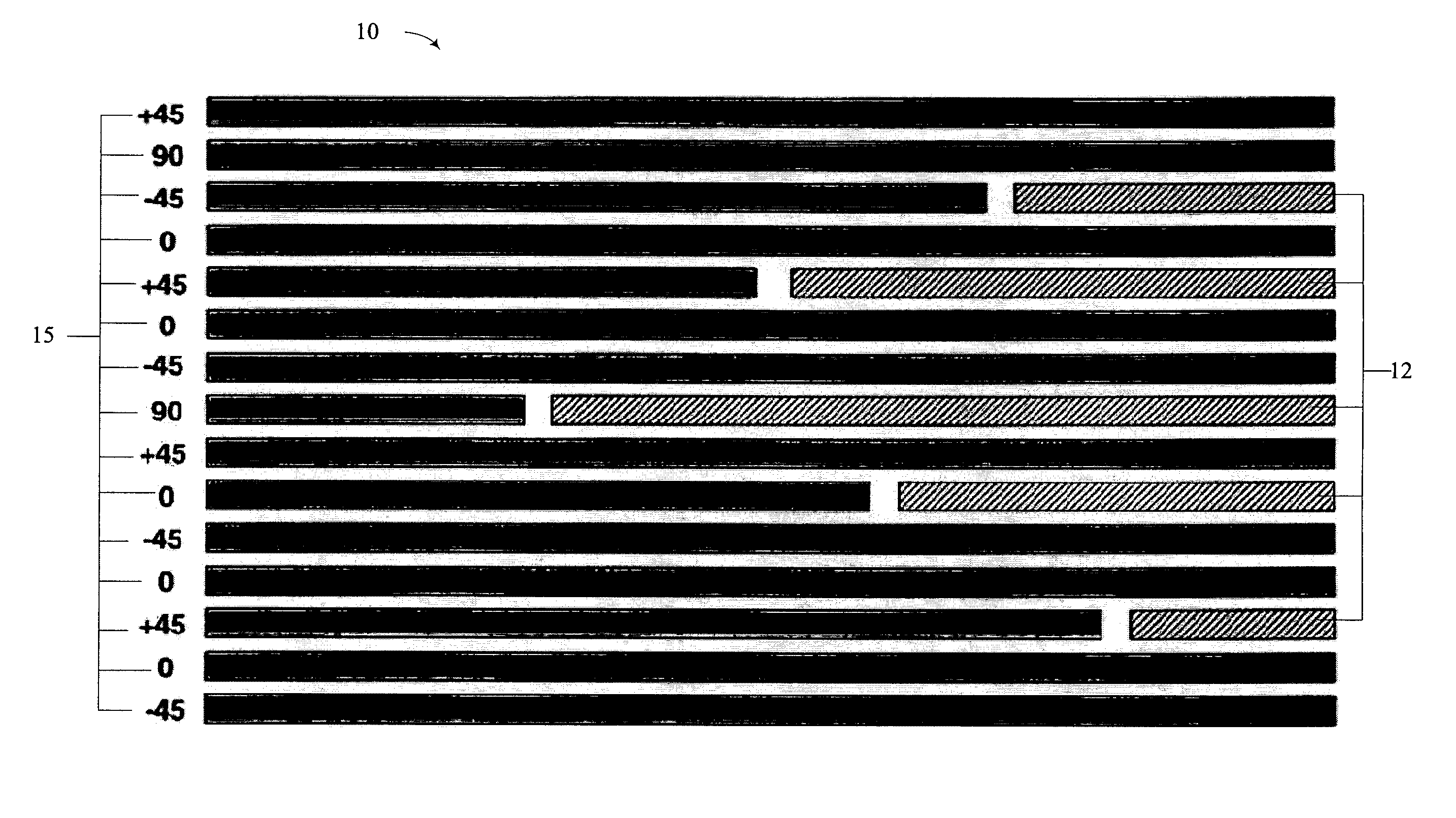
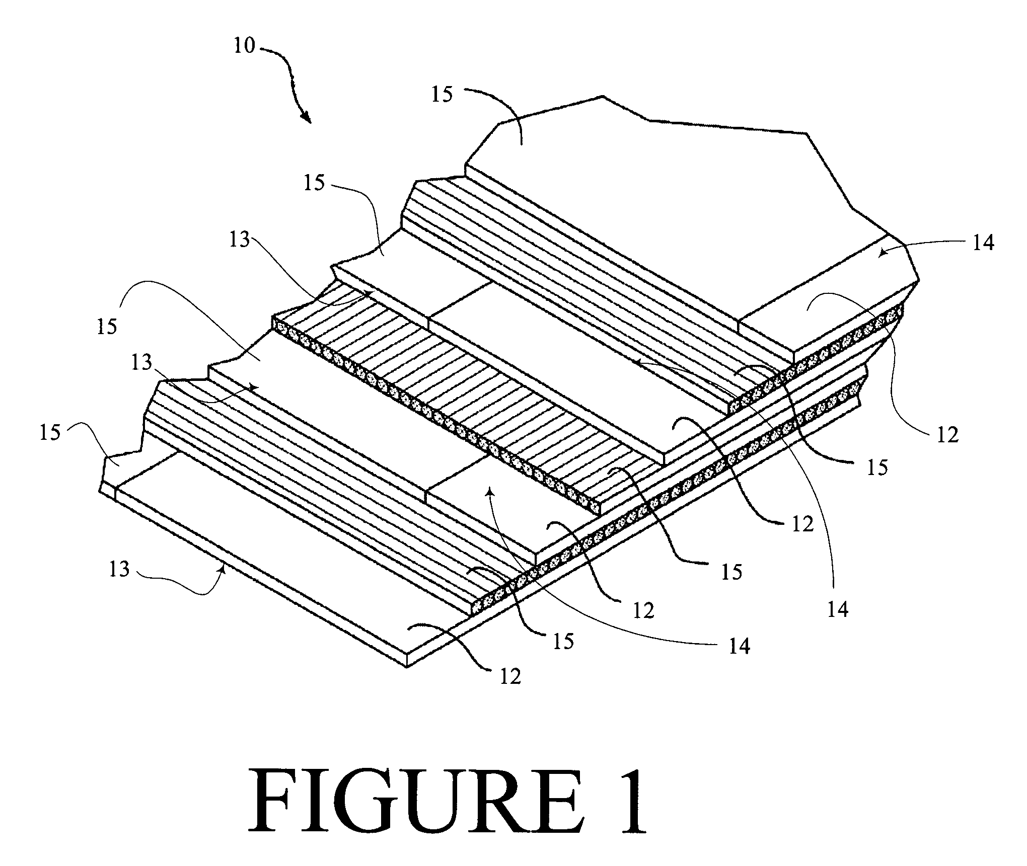
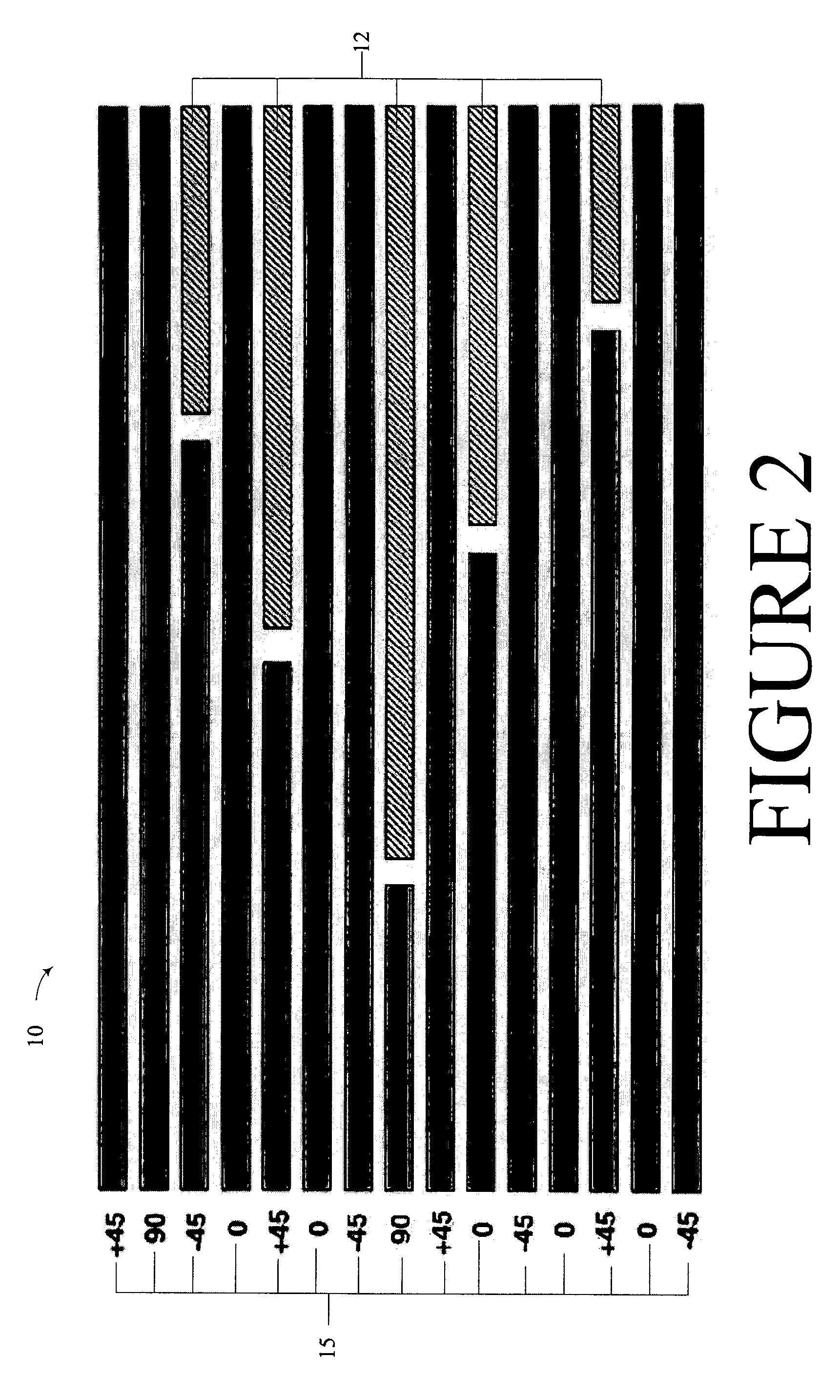
[0016]The present invention generally relates to laminate structures including a titanium layer, and methods of laying up the same. Many specific details of certain embodiments of the invention are set forth in the following description and in FIGS. 1–3 to provide a thorough understanding of such embodiments. One skilled in the art, however, will understand that the present invention may have additional embodiments, or that the present invention may be practiced without several of the details described in the following description.

[0017]By way of overview, in one embodiment in accordance with the present invention, a laminate structure includes a metal-polymer composite lamina. The metal-polymer composite lamina has a first face and a second face spaced apart, and extends to a terminal edge. The lamina includes a ply of fiber-reinforced polymer that extends between the first face and the second face and has an interior edge. The interior edge defines at least one cutout. A ply of me...


PUM

PropertyMeasurementUnit
thicknessaaaaaaaaaa
non-metallicaaaaaaaaaa
impart strengthaaaaaaaaaa

Abstract

Laminate structures and methods for forming same are disclosed. In one embodiment, a laminate structure includes a metal-polymer composite lamina. The metal-polymer composite lamina has a first face and a second face spaced apart, and extends to a terminal edge. The lamina includes a ply of fiber-reinforced polymer that extends between the first face and the second face and has an interior edge. The interior edge defines at least one cutout. A ply of metal foil extends between the first face and the second face substantially from the interior edge filling the at least one cutout.

Description

FIELD OF THE INVENTION[0001]This invention relates generally to aircraft skin panels of laminate structure and, more specifically, to introduction of foil into laminates to impart strength.BACKGROUND OF THE INVENTION[0002]Airframe manufacturers have found that skins of graphite, boron, or a blend of graphite and boron composite (collectively “polymeric composite”) unidirectional tape can be strengthened by the introduction of titanium foil between laid up plies of polymeric composite unidirectional tape. For example, U.S. Pat. No. 5,866,272 to Westre et al., incorporated by this reference, is one of several patents teaching the placement of titanium foil between plies of polymeric composite unidirectional tape.[0003]The resulting skin including a titanium foil makes up for a bearing deficiency of non-titanium containing polymeric composite panels, which ordinarily will not bear loads or hold pins well. In addition, composite construction is typically one-third of the density of tita...

Claims


Application Information

Patent Timeline
Patent Type & Authority Patents(United States)
IPC IPC(8): B32B3/12B32B15/08B32B3/14
CPCB32B3/14B32B15/08Y02T50/433Y10T428/24752Y10T156/1092Y10T156/1089Y10T428/1234Y10T428/192Y10T428/197Y10T428/12444Y10T156/1093Y10T156/109Y10T428/19Y02T50/40B32B2260/021B32B2260/046B32B38/08B32B7/12
Inventor WESTRE, WILLARDEVANS, DAVID W.LI, EDWARDPIEHL, MARC J.SAGER, ERIC
Owner THE BOEING CO
Why Eureka
Try Eureka