Resonant power source apparatus

a power source and auxiliary winding technology, applied in the direction of electric variable regulation, process and machine control, instruments, etc., can solve the problems of complex circuit, insufficient auxiliary winding for detecting voltage, and insufficient auxiliary winding for correctly detecting a period during which energy is supplied from the primary side to the secondary side, so as to reduce switching noise and switching loss, high efficiency, and low noise

Inactive Publication Date: 2006-10-03
SANKEN ELECTRIC CO LTD
View PDF3 Cites 15 Cited by
  • Summary
  • Abstract
  • Description
  • Claims
  • Application Information

AI Technical Summary

Benefits of technology

[0032]According to the present invention, a resonant power source apparatus that is highly efficient, low noise, inexpensive, simple, and capable of detecting a period during which energy is transferred from a primary side to a secondary side of a transformer and reducing switching noise and switching loss.

Problems solved by technology

On the other hand, the power source apparatus of FIG. 1 has a problem that the voltage VP1 of the primary winding P1 of the transformer T does not reach zero at the end of the period t1, and therefore, simply providing an auxiliary winding for detecting a voltage is insufficient to correctly detect a period during which energy is supplied from the primary side to the secondary side.
Detecting the energy supplying period with the use of a voltage on the secondary winding needs a complicated circuit because a signal detected on the secondary side must be insulated and transmitted to a controller that is on the primary side.

Method used


Image

  • Resonant power source apparatus
  • Resonant power source apparatus
  • Resonant power source apparatus

Examples


first embodiment

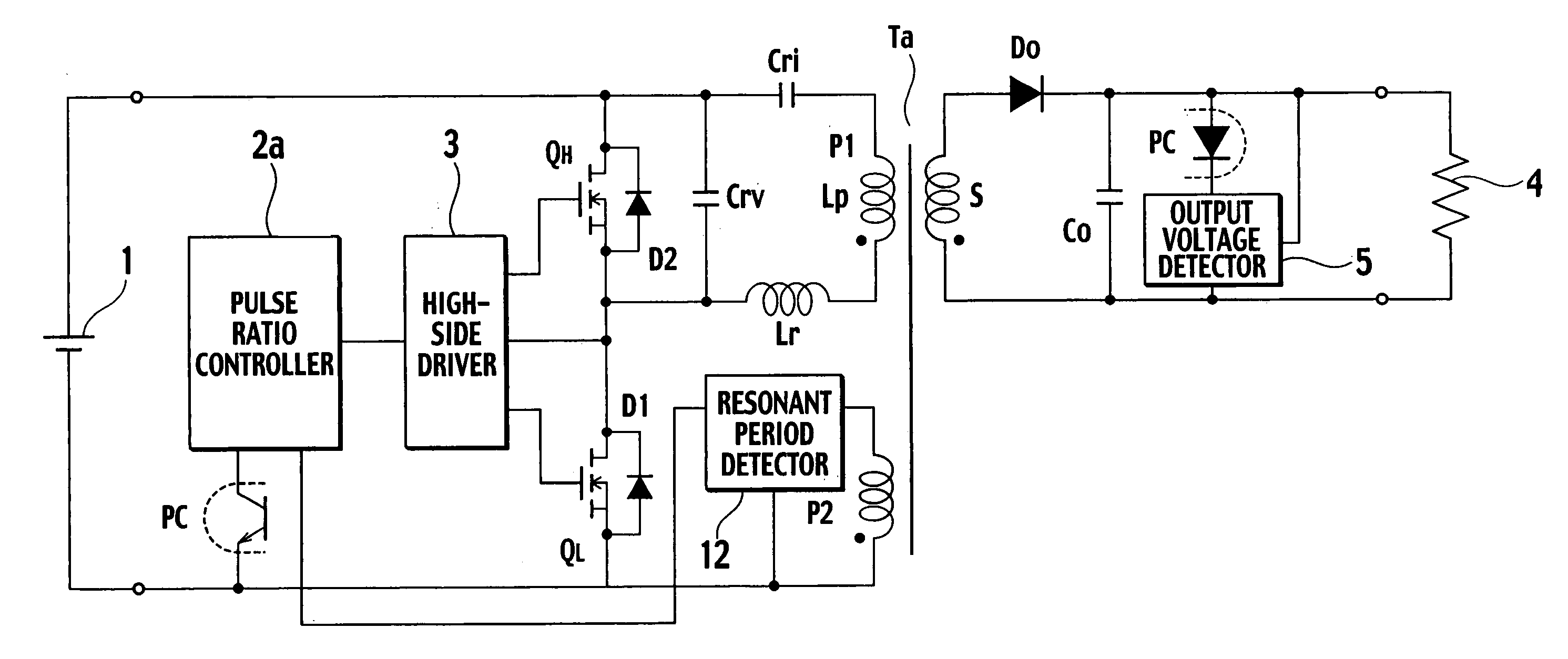
[0047]FIG. 4 is a circuit diagram showing a resonant power source apparatus according to the first embodiment of the present invention. Compared with the resonant power source apparatus of FIG. 1, the resonant power source apparatus of FIG. 4 additionally has an auxiliary winding P2 and a resonant period detector 12.

[0048]The auxiliary winding P2 is provided for a transformer Ta and is tightly coupled with a secondary winding S. The resonant period detector 12 detects, according to a voltage of the auxiliary winding P2 of the transformer Ta, a period during which energy is transmitted from the primary side to the secondary side of the transformer Ta and provides a resonant period detection signal to a pulse ratio controller 2a.

[0049]The pulse ratio controller (PRC) 2a receives a detected voltage from an output voltage detector 5 and carries out pulse ratio control to alternately turn on / off switching elements QL and QH, thereby maintaining a constant voltage for a load 4. The pulse...

second embodiment

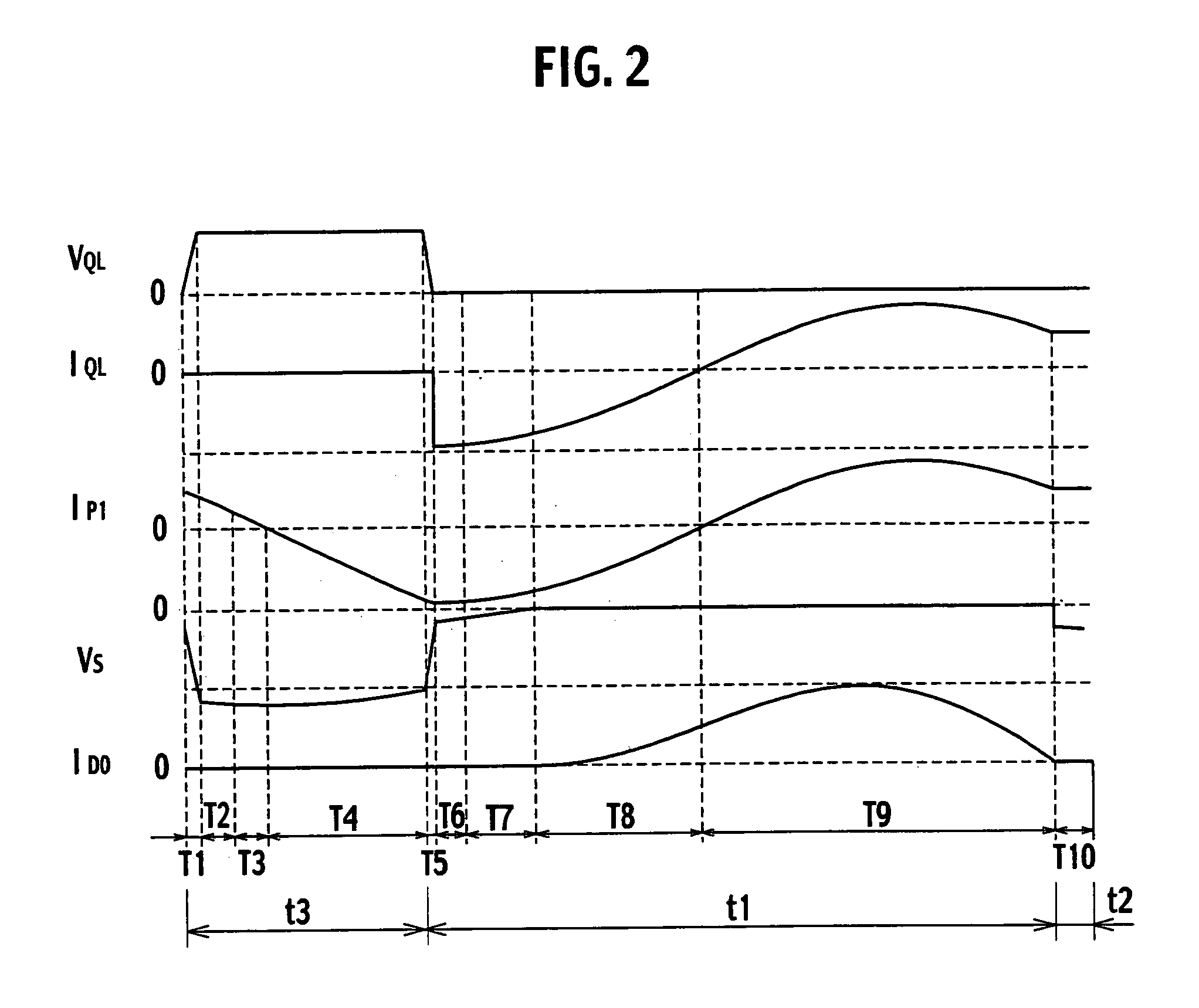
[0069]According to the resonant power source apparatus of the first embodiment, the auxiliary winding P2 is tightly coupled with the secondary winding S, and therefore, a resonant period detection signal from the resonant period detector 12 falls immediately at the end of a period during which energy is transmitted from the primary side to the secondary side of the transformer Ta. Due to the voltage-resonant capacitor Crv, each of the switching elements QL and QH turns on / off at a certain inclination. As a result, the resonant period detection signal rises at a certain inclination (i.e. out of plumb in a time chart which causes delay).

[0070]This inclination causes a problem of erroneously turning off the switching element QL. More precisely, upon receiving a gate signal, the switching element QL turns on to transmit energy to the secondary side of the transformer Ta. In a case where the above-mentioned inclination causes a delay in detecting the resonant period detection signal, the...


PUM


Abstract

A resonant power source apparatus has a series circuit of switching elements QL and QH connected to ends of a DC power source, a series circuit of a current-resonant capacitor, a resonant reactor, and a primary winding of a transformer connected to ends of the switching element QL or QH, a rectifying / smoothing circuit to rectify and smooth a voltage of a secondary winding, a pulse ratio controller to alternately turn on / off the switching elements QL and QH according to an output voltage from the rectifying / smoothing circuit, and a resonant period detector to detect a period during which energy is transmitted from the primary side to the secondary side of the transformer. The pulse ratio controller determines an ON period of the switching element according to a signal from the resonant period detector and an ON period of the switching element QH according to a signal from the rectifying / smoothing circuit.

Description

BACKGROUND OF THE INVENTION[0001]1. Field of the Invention[0002]The present invention relates to a resonant power source apparatus that is highly efficient, low noise, and inexpensive.[0003]2. Description of the Related Art[0004]FIG. 1 shows a current-resonant power source apparatus according to a related art. In FIG. 1, ends of a DC power source 1 are connected to a series circuit consisting of a MOSFET as a switching element QH and a MOSFET as a switching element QL. An end of the switching element QH is connected to a positive electrode of the DC power source 1. An end of the switching element QL is connected to a negative electrode of the DC power source 1.[0005]The switching element QH is connected in parallel with a diode D2. The switching element QL is connected in parallel with a diode D1. The switching element QH is connected in parallel with a voltage-resonant capacitor Crv.[0006]The voltage-resonant capacitor Crv is connected in parallel with a current-resonant circuit co...

Claims


Application Information

Patent Timeline
Patent Type & Authority Patents(United States)
IPC IPC(8): H02M3/335
CPCH02M3/33523H02M3/33569Y02B70/1433Y02B70/10H02M3/33571H02M3/015H02M3/01H02M3/28
Inventor OSAKA, SYOHEI
Owner SANKEN ELECTRIC CO LTD
Why Eureka
Try Eureka