Heat sinks for a cooler

a technology for heat sinks and coolers, applied in the direction of lighting and heating apparatus, semiconductor/solid-state device details, laminated elements, etc., can solve the problems of not being able to use heat sinks with miniature electronic devices, failing to provide sufficient heat exchange, etc., to improve heat exchange efficiency and increase heat exchange time

Inactive Publication Date: 2006-10-10
INVENTOR PRECISION
View PDF15 Cites 52 Cited by
  • Summary
  • Abstract
  • Description
  • Claims
  • Application Information

AI Technical Summary

Benefits of technology

[0006]An object of the present invention is to provide a heat sink having a base and a plurality of fins formed on a side of the base. A non-rectilinear air channel is defined between two adjacent fins for increasing the time for heat-exchange while the air is passing through the air channel, thereby improving the heat-exchange efficiency.

Problems solved by technology

Although the integrally formed heat sink / heat-dissipating fan has a simple structure and thus suitable for compact electronic devices, the airflow for carrying the heat generated by the heat-dissipating fan is apt to quickly pass the respective rectilinear air channel 12a and thus fails to provide sufficient time for heat-exchange.
As a result, the heat sink could not be used with miniature electronic devices.
Further, the air flow for carrying the heat generated by the heat-dissipating fan is apt to quickly pass the respective rectilinear air channel 12a and thus fails to provide sufficient time for heat-exchange.

Method used


Image

  • Heat sinks for a cooler
  • Heat sinks for a cooler
  • Heat sinks for a cooler

Examples


Embodiment Construction

[0025]Preferred embodiments of the present invention are now to be described hereinafter in detail, in which the same reference numerals are used in the preferred embodiments for the same parts as those in the prior art to avoid redundant description.

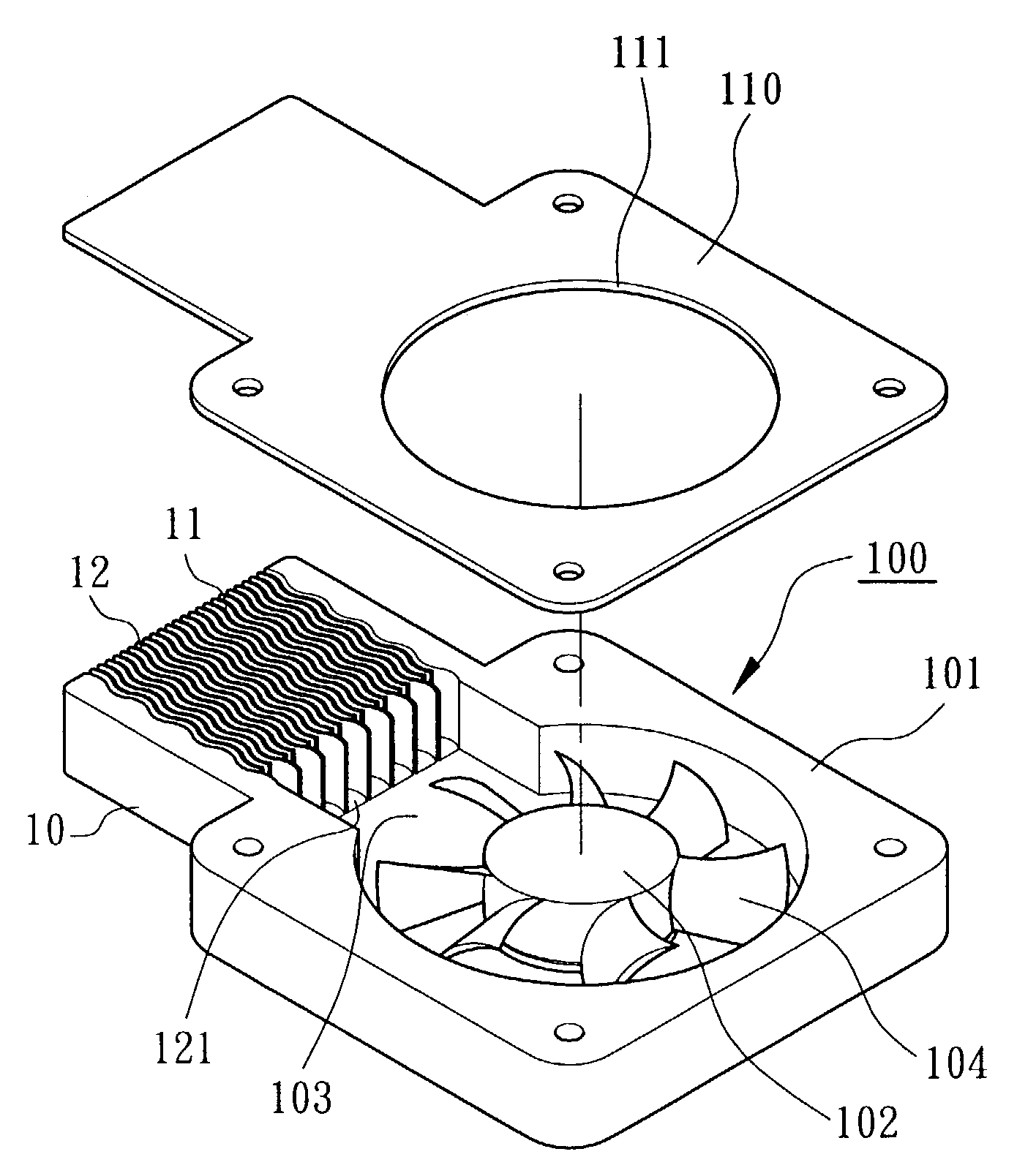
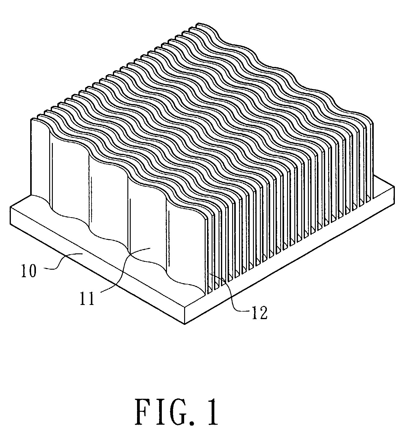
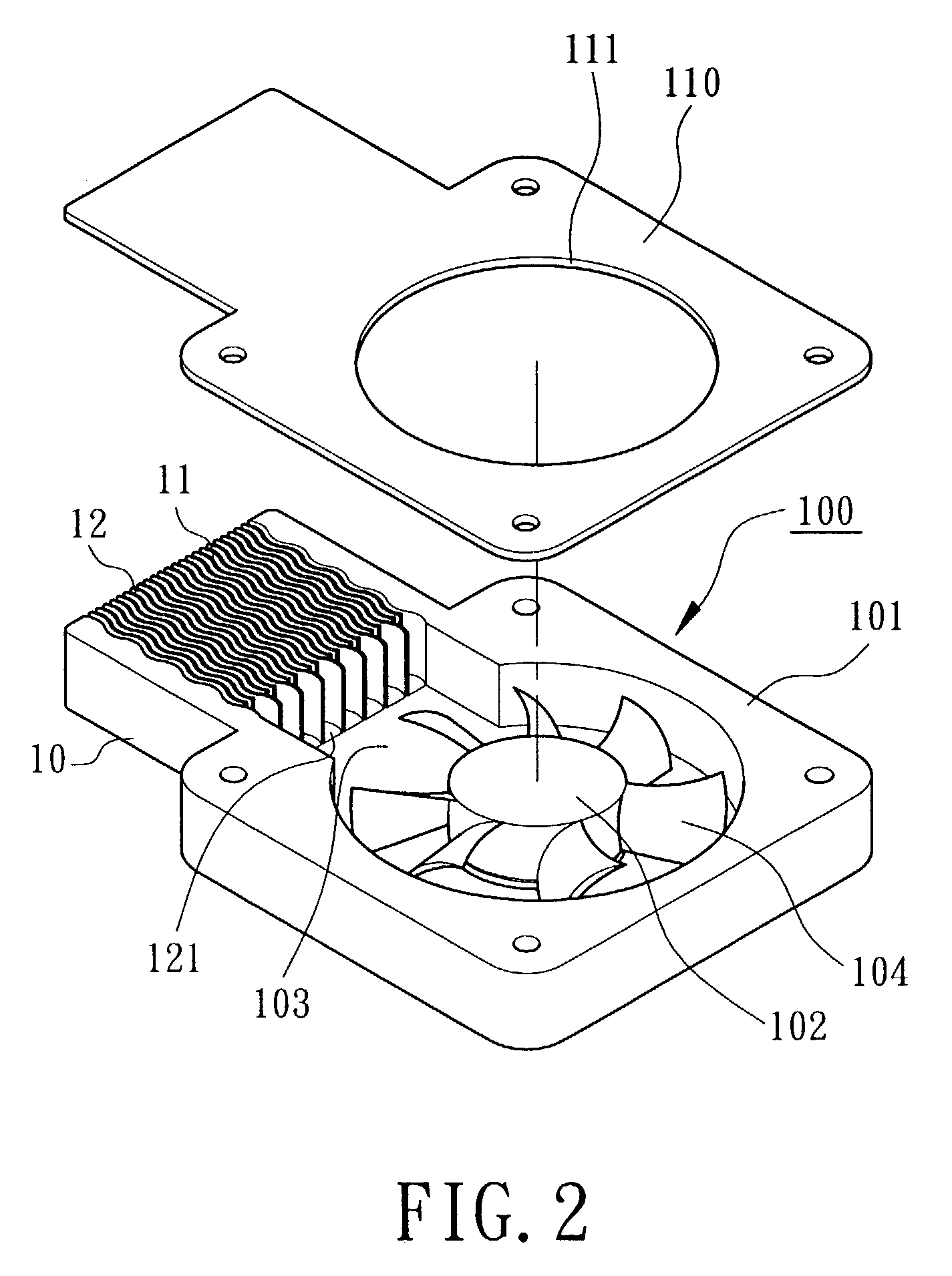
[0026]Referring to FIG. 1, a heat sink of an embodiment of the present invention includes a base 10 and a plurality of fins 11 formed on a side (e.g., upper side) of the base 10. A non-rectilinear air channel 12 is defined between two adjacent fins 11. The heat sink is made of a heat-conductive material such as copper, aluminum, etc. An underside of the base 10 is in contact with a heat-generating electronic element (not shown). The fins 11 extend along a longitudinal direction or a lateral direction of the base. Preferably, the fins 11 are wavy to form a wavy air channel 12 between two adjacent fins 11. In this embodiment, the wavy fins 11 are continuous and parallel to each other. The wavy fins 11 are spaced at regular intervals or ir...


PUM


Abstract

A heat sink includes a base having a first side in contact with a heat-generating electronic element and a second side opposed to the first side. Fins are formed on the second side of the base. A non-rectilinear air channel is formed between two adjacent fins, with a length of the non-rectilinear air channel being greater than a length of the base along an extending direction of the fins on the base. The heat sink may be provided to an outlet side of a heat-dissipating fan to form a cooler.

Description

BACKGROUND OF THE INVENTION[0001]1. Field of the Invention[0002]The present invention relates to heat sinks for a cooler. In particular, the present invention relates to heat sinks for a cooler, wherein the heat sinks have a plurality of wavy or zigzag fins formed on a base, forming a non-rectilinear air channel between each two adjacent fins. The present invention also relates to coolers incorporating the heat sinks.[0003]2. Description of Related Art[0004]FIG. 12 illustrates a conventional cooler comprised of a heat-dissipating fan 100 and a heat sink. The heat sink includes a base 10 and a plurality of fins 11a formed on an upper side thereof, thereby defining a plurality of air channels 12a. The underside of the base 10 is secured to a heat-generating electronic element (not shown). The heat-dissipating fan 100 includes a metal casing 101 that is integrally formed with the base 10. A fan wheel 102 is mounted in the metal casing 101, and a lid or cover 110 is mounted to the casin...

Claims


Application Information

Patent Timeline
Patent Type & Authority Patents(United States)
IPC IPC(8): F28D15/00H05K7/20F28F3/04H01L23/367H01L23/467
CPCF28F3/04H01L23/3672H01L23/467H01L2924/0002H01L2924/00F28F13/06
Inventor CHEN, CHIEN-YU
Owner INVENTOR PRECISION
Why Eureka
Try Eureka