
Sequential color recapture for image display systems

a color recapture and image technology, applied in the field of sequential color recapture in the scrolling color projection system, to achieve the effect of improving illumination efficiency characteristics, reducing cost, and improving illumination efficiency

Inactive Publication Date: 2006-10-10
TEXAS INSTR INC
View PDF41 Cites 12 Cited by
  • Summary
  • Abstract
  • Description
  • Claims
  • Application Information

AI Technical Summary

Benefits of technology

This approach results in brighter images with longer lamp life, reduced system volume and mass, lower costs, and improved contrast by utilizing all light sources efficiently, reducing the need for cooling systems.

Problems solved by technology

Thus, substantially brighter images may be projected by a single modulator panel display system, and the system may replace three panel display systems that are more costly to implement than a single panel display system.

Method used


Image

  • Sequential color recapture for image display systems
  • Sequential color recapture for image display systems
  • Sequential color recapture for image display systems

Examples


Embodiment Construction

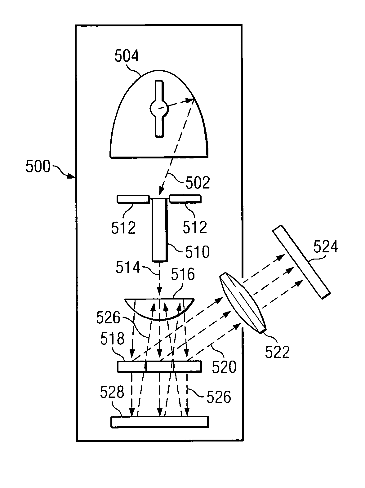
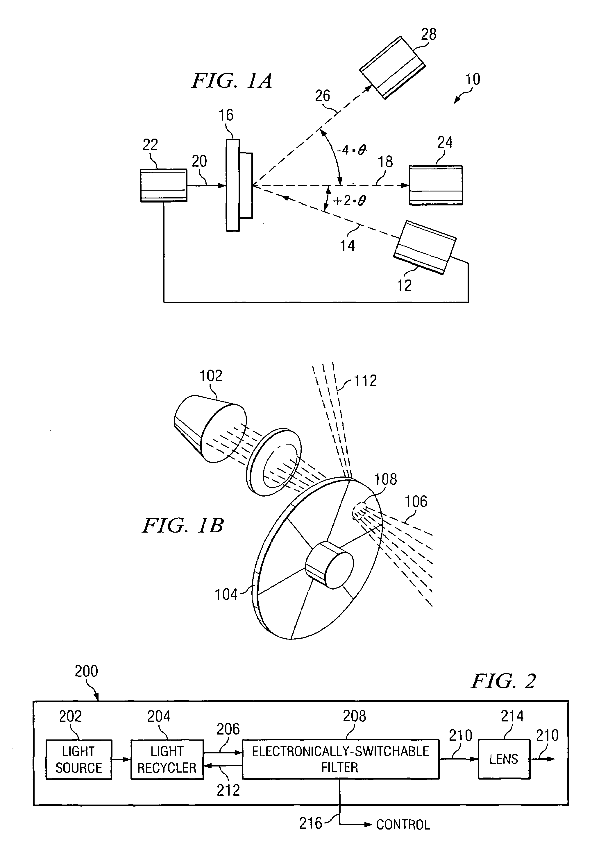
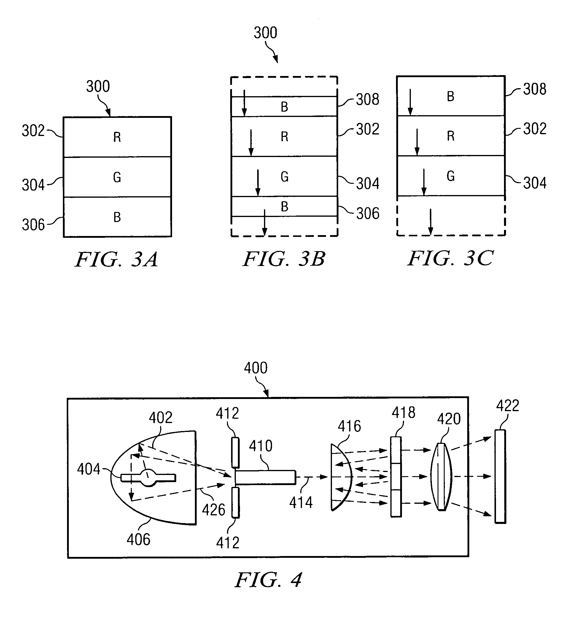
[0018]A new optical system and method have been developed that dramatically improve the optical efficiency of single-panel sequential color display systems. The system uses a sequential color concept called falling raster or scrolling color in which the illumination beam laterally changes color. Specifically, an electronically-switchable filter may be used in combination with a light recycler to provide for the recycling of light that is not initially acceptable to the system for producing an image. In particular embodiments, for example, light that is initially rejected by the electronically-switchable filter may be collected and re-presented to the filter one or more times until the light is accepted by the filter. Specifically, where the electronically-switchable filter includes multiple scrolling colors that are displayed at any one time, light rejected by one filter segment during the first presentation of the light to the filter may be passed by another filter segment on a sub...


PUM


Abstract

A method for transmitting light in an image display system includes generating a beam of light from a light source. The beam of light is directed at a first segment of an electronically-switchable filter. A first portion of the beam of light is accepted by the first segment of the electronically-switchable filter, and a second portion of the beam of light is rejected by the first segment of the electronically-switchable filter. The first portion of the light beam is modulated to produce at least a portion of a displayed image. The second portion of the light beam is recycled to redirect the second portion of the light beam at a second segment of the electronically-switchable filter. The second portion of the light beam is accepted by the second segment of the electronically-switchable filter. The second portion of the light beam is modulated to produce at least a portion of the displayed image.

Description

RELATED APPLICATIONS[0001]This application is a continuation-in-part of U.S. patent application Ser. No. 10 / 910,206 filed Aug. 3, 2004, and entitled “COLOR RECAPTURE FOR DISPLAY SYSTEMS,” which is a divisional of U.S. patent application Ser. No. 09 / 705,467, filed Nov. 3, 2000, now U.S. Pat. No. 6,771,325, entitled “COLOR RECAPTURE FOR DISPLAY SYSTEMS,” which claims the benefit of U.S. Provisional Patent Application No. 60 / 173,640 filed Dec. 30, 1999, entitled “SEQUENTIAL COLOR RECAPTURE FOR SINGLE-MODULATOR PROJECTION SYSTEMS” and U.S. Provisional Patent Application No. 60 / 163,866 filed on Nov. 5, 1999, entitled “SEQUENTIAL COLOR RECAPTURE FOR SINGLE-MODULATOR PROJECTION SYSTEMS.”TECHNICAL FIELD OF THE INVENTION[0002]This invention relates in general to image display systems, and more particularly to sequential color recapture in a scrolling color projection system including a scrolling electronically-switchable filter.BACKGROUND[0003]Spatial light modulators used in sequential colo...

Claims


Application Information

Patent Timeline
Patent Type & Authority Patents(United States)
IPC IPC(8): G03B21/00G02B21/14G03B21/28H04N5/74H04N9/12G03B21/14H04N9/31
CPCH04N9/3117H04N9/315H04N9/3197
Inventor DAVIS, MICHAEL T.PENN, STEVEN M.
Owner TEXAS INSTR INC
Learn More