Eureka AIR delivers breakthrough ideas for toughest innovation challenges, trusted by R&D personnel around the world.

Sliding member and method of manufacturing the same

a technology of sliding member and sliding surface, which is applied in the direction of sliding contact bearings, connecting rod bearings, machines/engines, etc., can solve the problems of generating rapid increase in high load on a part of its sliding surface, and it is difficult to maintain the oil film between the sliding surface, so as to prevent the holes from overlapping with each other and from being deformed

Inactive Publication Date: 2006-10-10
DAIDO METAL CO LTD
View PDF8 Cites 10 Cited by
  • Summary
  • Abstract
  • Description
  • Claims
  • Application Information

AI Technical Summary

Benefits of technology

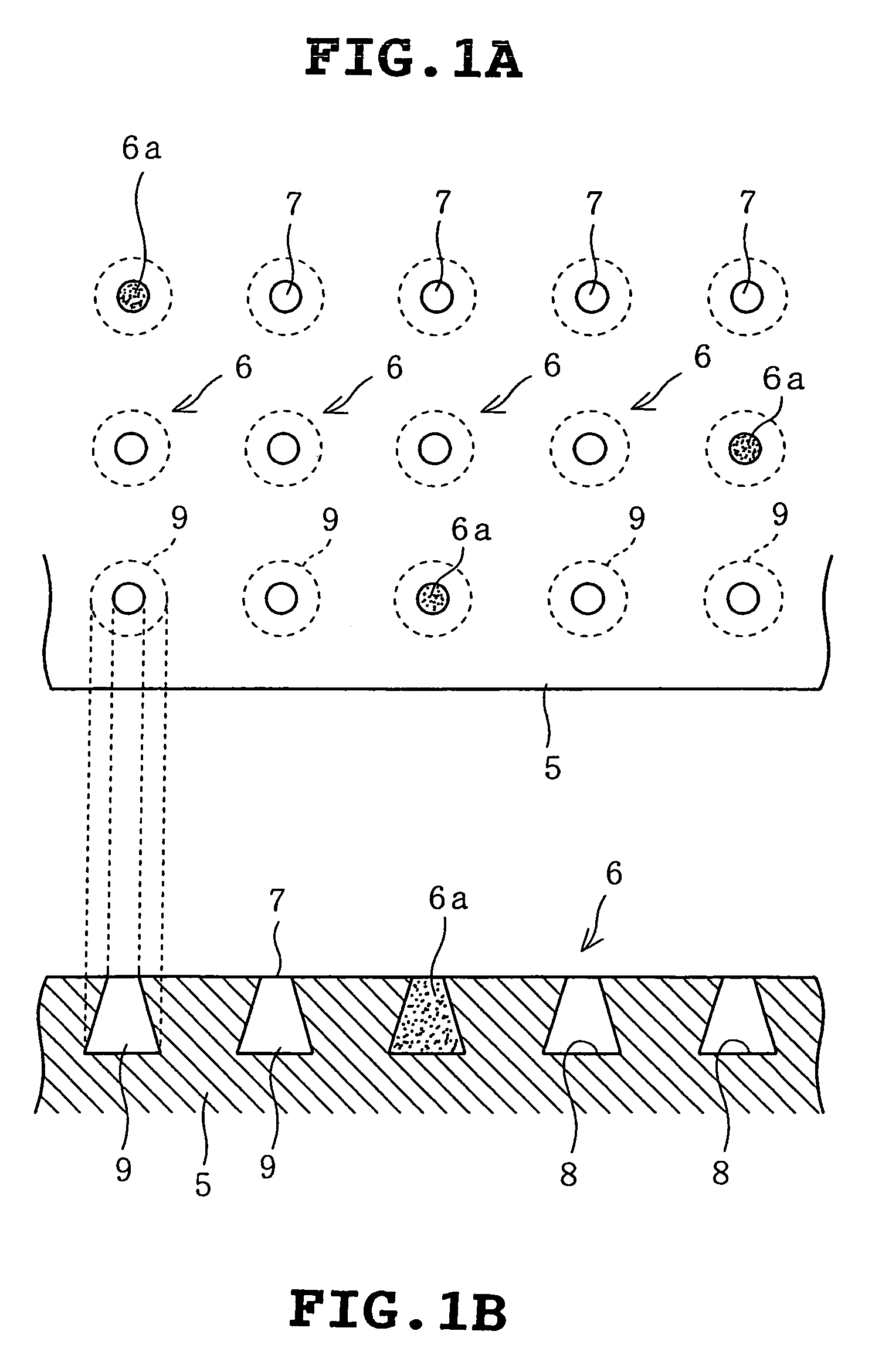
[0010]According to the first aspect of the invention, the hole is configured such that its interior is large as compared with its opening end. Therefore, when a load applied on the sliding member by the mating member is increased, a surface load of the sliding surface is increased so that lubricating oil forming an oil film between sliding surfaces is intensely pressed to be confined in the hole. Then, the pressure of the lubricating oil present in the hole is increased, which causes a phenomenon that the increased pressure is transmitted to the lubricating oil forming the oil film. As a result, even when the load applied by the mating member is rapidly increased, the oil film is increased in pressure in accordance with the increased load, so that breakage of the oil film does not occur and a favorable lubricating state can be maintained.
[0023]According to the seventh aspect of the invention, it is possible to irradiate the laser beam in an optimum range for forming the holes on the sliding surface. Therefore, it is also possible to prevent the holes from overlapping with each other and from being made deformed.

Problems solved by technology

However, in the case of a sliding member used for supporting a connecting rod, for example, a rapidly increasing high load is often generated on a part of its sliding surface.
Under such working condition, since each of the holes for retaining the lubricating oil of the sliding member disclosed in JP-A-2002-147459 has a bowl-shape, the lubricating oil is easily flipped from the respective holes and flows out from a hole to a hole by virtue of the holes being contiguous to one another, so that it becomes difficult to maintain the oil film between the sliding surfaces, after all.

Method used


Image

  • Sliding member and method of manufacturing the same
  • Sliding member and method of manufacturing the same
  • Sliding member and method of manufacturing the same

Examples


Embodiment Construction

[0035]Hereinafter, a first embodiment in which a sliding member according to the invention is applied to a bearing (referred below to as a crank-pin bearing) mounted on a large end constituting a connecting rod for an automobile will be described with reference to FIGS. 1 to 6.

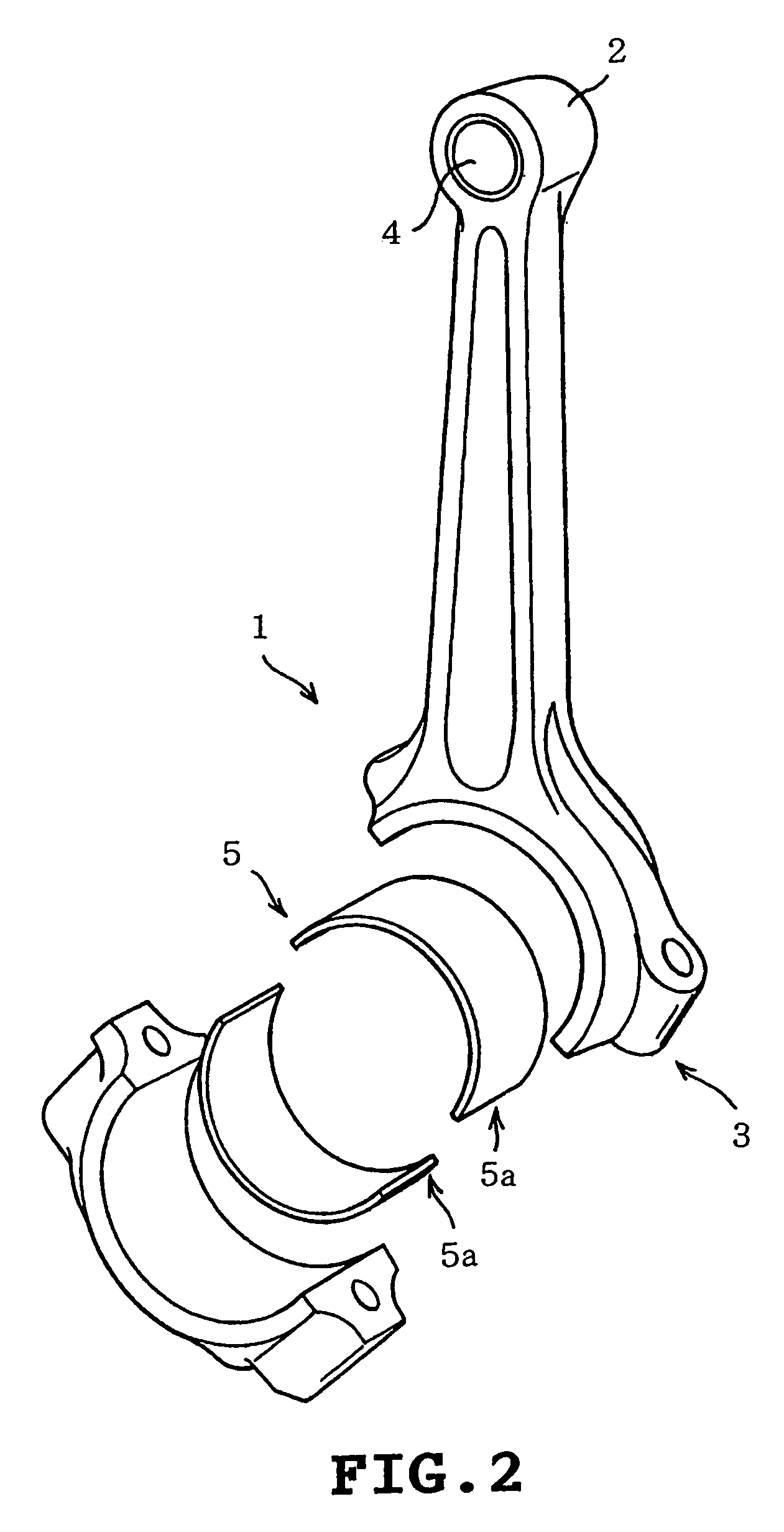
[0036]As shown in FIG. 2, a connecting rod 1 includes both lengthwise ends, of which one is a small end 2 connected to a piston pin, and of which the other is a large end 3 connected to a crank pin. On the both ends 2 and 3, a piston-pin bearing 4 and a crank-pin bearing 5 are mounted for supporting the piston pin and the crank pin, respectively.

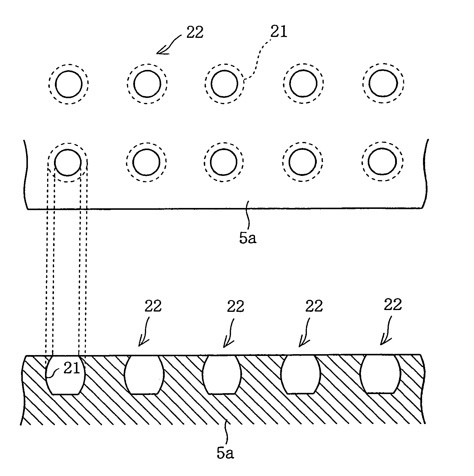
[0037]The crank-pin bearing 5 is constructed in a cylindrical shape by putting two semi-cylindrical shaped half bearings 5a together. The half bearings 5a are constituted by mounting bearing alloy on steel back metal, and a large number of holes 6 which are aligned lengthwise and crosswise are formed on a whole sliding surface (a surface of the bearing alloy) thereof, ...


PUM


Abstract

The invention provides a sliding member including a plurality of holes formed on a sliding surface thereof, which sliding surface is adapted to slide on a mating member, at least one of the holes having an enlarged portion in at least a portion between an opening end and a bottom end thereof, the enlarged portion being larger than the opening end on the sliding surface.

Description

CROSS-REFERENCE TO RELATED APPLICATIONS[0001]This application claims priority based on Japanese Patent Application No. 2003-102886, filed Apr. 7, 2003, the entirety of which is incorporated herein by reference.BACKGROUND OF THE INVENTION[0002]The present invention relates to a sliding member used for a connecting rod for example, of which a sliding surface is subjected to a high surface load.[0003]An engine used in an automobile, etc., converts up-and-down motion of a piston caused by explosion power of petroleum base fuel into rotational movement through a connecting rod and a crankshaft, to provide rotational driving power. The piston, connecting rod, crankshaft or the like are connected with each other through a shaft accommodated in a bearing, and a sliding surface of the bearing is repeatedly subjected to a rapidly increasing high load from the shaft as a mating member, during operation of the engine.[0004]However, when the mating member and the bearing slide relative to each o...

Claims


Application Information

Patent Timeline
Patent Type & Authority Patents(United States)
IPC IPC(8): F16C17/00F02F1/20F16C9/04F16C33/10F16C33/14
CPCF02F1/20F16C9/04F16C33/103F16C2240/44F16C2240/40
Inventor FUJITA, MASAHITOTSUJI, HIDEOSHIBAYAMA, TAKAYUKI
Owner DAIDO METAL CO LTD
Why Eureka
Eureka Blog
Learn More