Electric cooling fan and case of electronic or electric device

a cooling fan and electric technology, applied in the direction of machines/engines, stators, liquid fuel engines, etc., can solve the problems of large noise, insufficient measurement, and disturbance of smooth exhausting of air, and achieve the effect of low noise level, and efficient intake or exhaust air

Active Publication Date: 2006-10-10
NIDEC CORP
View PDF14 Cites 14 Cited by
  • Summary
  • Abstract
  • Description
  • Claims
  • Application Information

AI Technical Summary

Benefits of technology

[0009]An object of the present invention is to provide a case for an electronic or electric device having a fan motor that can an intake or exhaust air efficiently at a low noise level through an air intake or exhaust opening with a finger guard. Another object of the present invention is to provide a fan motor with a finger guard on the fan motor frame that can intake or exhaust air efficiently at low noise level.
[0010]The present invention is characterized in a shape of a cross section of each rib constituting a finger guard that is provided in an airflow path of a cooling fan. According to one aspect of the present invention, the finger guard includes plural first ribs extending in the lateral direction and plural second ribs extending in the vertical direction. The cross section shape of each of the first and second ribs has an inclined surface that is substantially parallel to or along the direction of the airflow that is drawn in or exhausted from a fan motor as being rotated spirally. Another finger guard according to the present invention has ribs formed like a grid or a mesh, and the cross section shape of each of the ribs has at least one inclined surface that is substantially parallel to or along the direction of the airflow that is drawn in or exhausted from the fan motor as being rotated spirally. In this way, the intake or exhaust airflow is not disturbed so that generation of air turbulence can be prevented. As a result, cooling efficiency can be improved and generation of noise can be suppressed.

Problems solved by technology

However, the mesh finger guard attached to the opening as an exhaust hole for the cooling fan may disturb smooth exhausting of air inside the case since the exhaust air may be interrupted by the finger guard.
There is another problem that large noise may be generated when the exhaust air is interrupted by the finger guard.
However, this measure is not still a sufficient for achieving substantial improvement against the above-mentioned problem.
However, available finger guards up to now cannot satisfy such demands sufficiently.

Method used


Image

  • Electric cooling fan and case of electronic or electric device
  • Electric cooling fan and case of electronic or electric device
  • Electric cooling fan and case of electronic or electric device

Examples


first embodiment

[0026](First Embodiment)

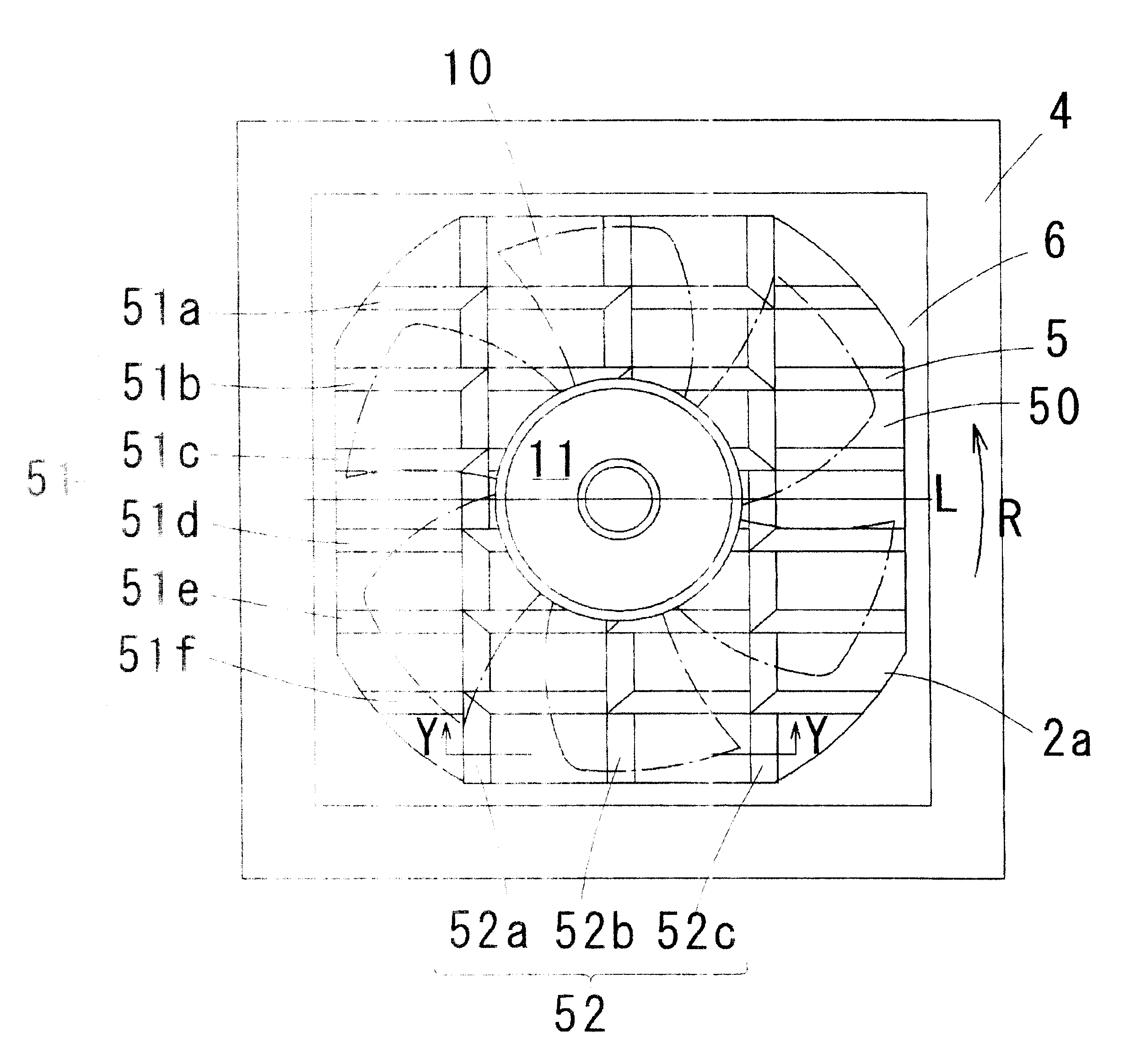
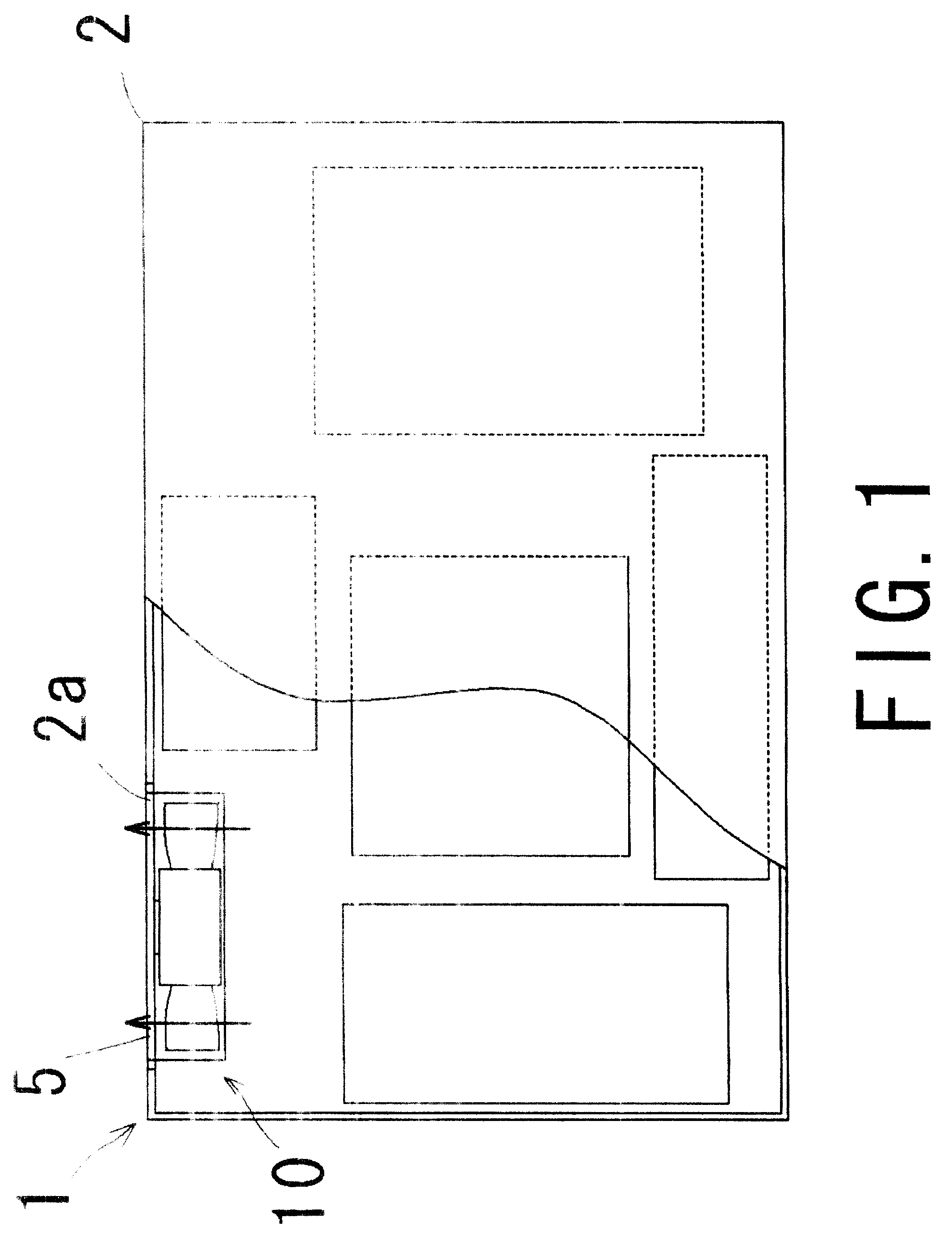
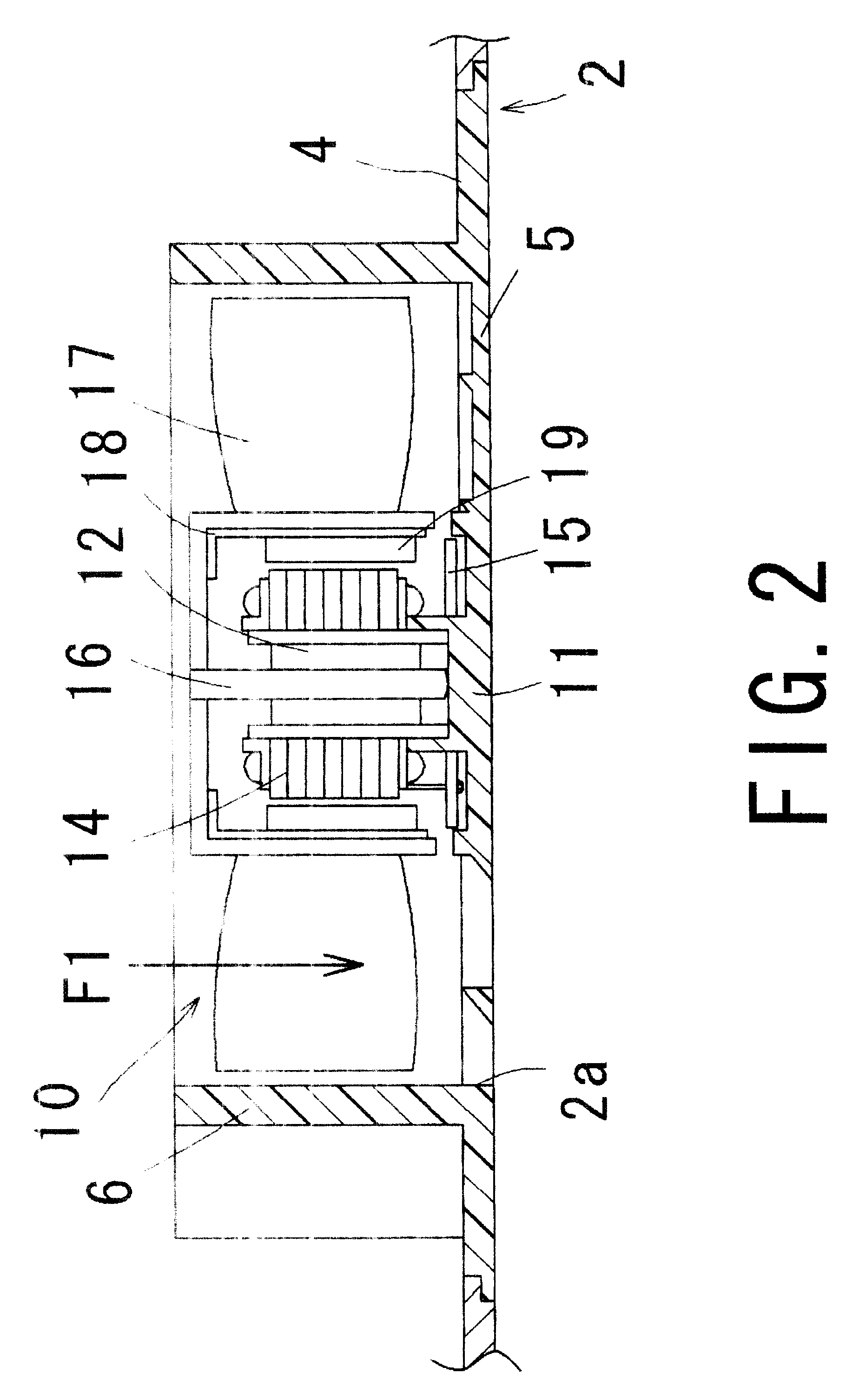
[0027]A first embodiment of the present invention will be explained with reference to FIGS. 1–4. FIG. 1 is a plan view that shows an inner structure of the electronic or electric device schematically. FIG. 2 is a cross section of a main portion of a fan motor that is included in the device. FIG. 3 is a cross section of a main portion cut along the Y—Y line in FIG. 4. FIG. 4 is a plan view of a main portion in which an opening portion of the case of the electronic or electric device shown in FIG. 1 is viewed from the inside toward the outside.

[0028][Electronic or Electric Device]

[0029]As shown in FIG. 1, an electronic or electric device 1 of the first embodiment is a main body of a desktop type personal computer, for example. A cooling fan motor 10 is provided in the case 2. The fan motor 10 is arranged at the inside and a vicinity of an opening portion 2a that is formed in the side wall of the case, so as to exhaust air inside the case 2 through the opening p...

second embodiment

[0052](Second Embodiment)

[0053]In the first embodiment, the cylindrical portion 6 surrounding the fan motor 10 is formed integrally with the sub panel 4. The second embodiment, however, is different from the first embodiment in that the cylindrical portion 6 is made as another member (hereinafter, referred to as a cylindrical member 61) separated from the sub panel 4 as shown in FIG. 6. As shown in FIG. 6, the cylindrical member 61 is similar to the cylindrical portion 6, but includes an inclined surface 41a in which the inner end portion of the opening portion 2a side enlarges the diameter to the opening portion 2a side. The cylindrical member 61 is fastened to the sub panel 4 by a screw. By providing this inclined surface 41a, air flows smoothly from the fan motor 10 to the opening portion 2a, so that airflow characteristics is improved.

[0054]This inclined surface 41a can be formed more easily than the first embodiment by structuring it as the cylindrical member 61 separated from ...

third embodiment

[0055](Third Embodiment)

[0056]In the first and the second embodiments, the fan motor 10 is supported by the motor supporting portion 11 of the finger guard 5. In third embodiment, the structure for supporting the fan motor 10 is different from the first and the second embodiments. Namely, the fan motor 10 of the third embodiment is supported by the conventional housing 70 as shown in FIG. 7. The housing 70 constitutes a motor supporting portion 72 by ribs 83 that extend radially inside the cylindrical portion. The side wall of the case 2 is provided with an opening portion 2a having a finger guard 75 similarly to the first and the second embodiments as shown in FIG. 8. The finger guard 75 as shown in FIG. 8 has a structure of the rib that is similar to the first and the second embodiments except for the motor supporting portion (the circle in the middle in FIG. 8 is a portion only for sticking a rating plate).


PUM


Abstract

A case that is used for an electronic or electric device has an opening portion arranged at a vicinity of a fan motor that generates airflow inside and outside the case. The opening portion has a protection portion for preventing a finger or other matters from entering the fan motor. The protection portion includes a first rib group extending linearly in a lateral direction, a second rib group extending linearly in a second direction vertical direction. Each of the ribs has an inclined surface that is along a direction of the airflow exhausted from the fan motor and faces the inside or the outside of the opening portion.

Description

BACKGROUND OF INVENTION[0001]1. Field of the Invention[0002]The present invention relates to an electronic or electric device such as a personal computer, a computer game machine or a printer, which has a cooling fan housed in a case. The present invention also relates such a cooling fan and a case used for the electric device.[0003]2. Description of the Prior Art[0004]An electronic or an electric device such as a personal computer, a computer game machine or a printer includes various electromechanical parts housed in a case. Since the inside of the case becomes high temperature due to heat generated by a CPU and / or IC chips, or electromechanical parts, a cooling fan is disposed in the case. This fan is usually arranged at a vicinity of an opening (an exhaust hole) formed in the side-wall of the case. The inside air of the case is exhausted through this opening externally, so that the inside of the case is cooled.[0005]This opening is usually provided with a mesh guard that is call...

Claims


Application Information

Patent Timeline
Patent Type & Authority Patents(United States)
IPC IPC(8): F01D1/02F04D29/70F04D29/54
CPCF04D29/703F04D29/542F04D29/544
Inventor TAKEMOTO, SHINJI
Owner NIDEC CORP
Why Eureka
Try Eureka