Arrangement for controlling airflow for example in clean rooms

a technology for controlling airflow and clean rooms, which is applied in the field of ventilation installation in buildings, can solve the problems of air filtering, reducing air volume, and difficulty in completely sealing rooms, and achieves the effects of avoiding excess pressure, simple and reliable manner, and high security

Inactive Publication Date: 2006-10-10
BJORDAL ODDVAR INGE
View PDF5 Cites 9 Cited by
  • Summary
  • Abstract
  • Description
  • Claims
  • Application Information

AI Technical Summary

Benefits of technology

[0008]A first objective of the invention is to obtain a device that in a simple and reliable manner can achieve high security for a suitable difference of pressure between rooms having different content in the air. This can be achieved even with a high degree of clogging of filters / channels or other forms of strong reduction in the function of the ventilation system. In a sub-pressure isolation room, for example, it would be possible to avoid excess pressure even if the ventilating fan stops and the supply air fan still functions. Even with a very simple / small back-up ventilating fan or local recycling arrangement, it would be possible to maintain a certain degree of sub-pressure.

Problems solved by technology

Such additives can in themselves cause problems if allowed to spread to the cleaner area.
In practice, it is difficult to completely seal rooms.
A problem in this situation is that air filters that are often used in the airflow from the polluted side become clogged and the amount of air decreases.
Control of small differences in pressure is difficult.
Another source of pressure reversal is failure in the part of the ventilation system (fan) that contributes to a functional difference in pressure, while the opposite port is intact.
Therefore, expensive backup systems are built to take over in case of failure.
All in all, the backup systems that shall secure the actual functions will contribute with a considerable share of the total costs.
The reason for this is that current systems, in their basic function, without further security measures, have a limited functional security.
In practice, this is too expensive, and when considering whether to protect the patient or the surroundings, the patient loses and is placed in isolation with sub-pressure.
The calculated minimum leakage then provides extra supply of polluted air, and is in such cases a disadvantage.
Corresponding problems are also present in relation to surgery on infectious patients and other situations.
Access paths present a problem.
Considering the large area represented by a door, this can amount to considerable amounts of air.
Even minor differences in temperature between the rooms can contribute to this leakage becoming quite substantial.
By waiting in the sluice, the content of the infection can be diluted, but often there are limited amounts of air accessible, so it takes a long time to attain practical dilution.
Such a waiting period feels bothersome to the personnel (and is therefore ignored), and it is expensive to have personnel waiting.
When moving in and out, industry has similar problems as to those of the health service.
This can have fatal consequences in the case of fire and smoke, as smoke and gases from the corridor are drawn directly into the sub-pressure room.

Method used


Image

  • Arrangement for controlling airflow for example in clean rooms
  • Arrangement for controlling airflow for example in clean rooms
  • Arrangement for controlling airflow for example in clean rooms

Examples


Embodiment Construction

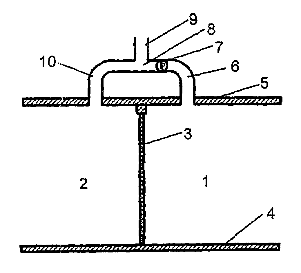
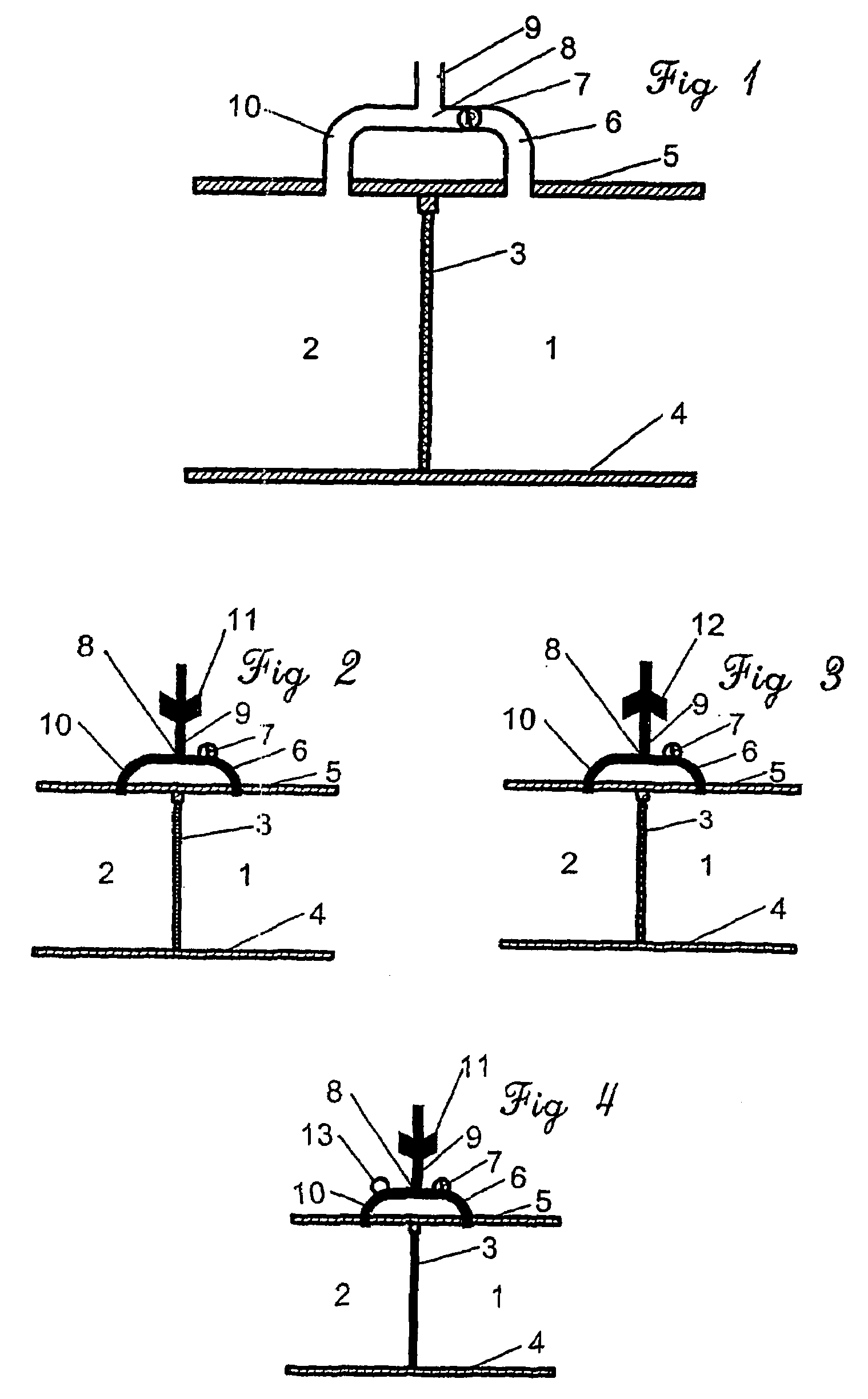
[0028]Initially, the invention will be discussed in terms of the sketch shown in FIG. 1.

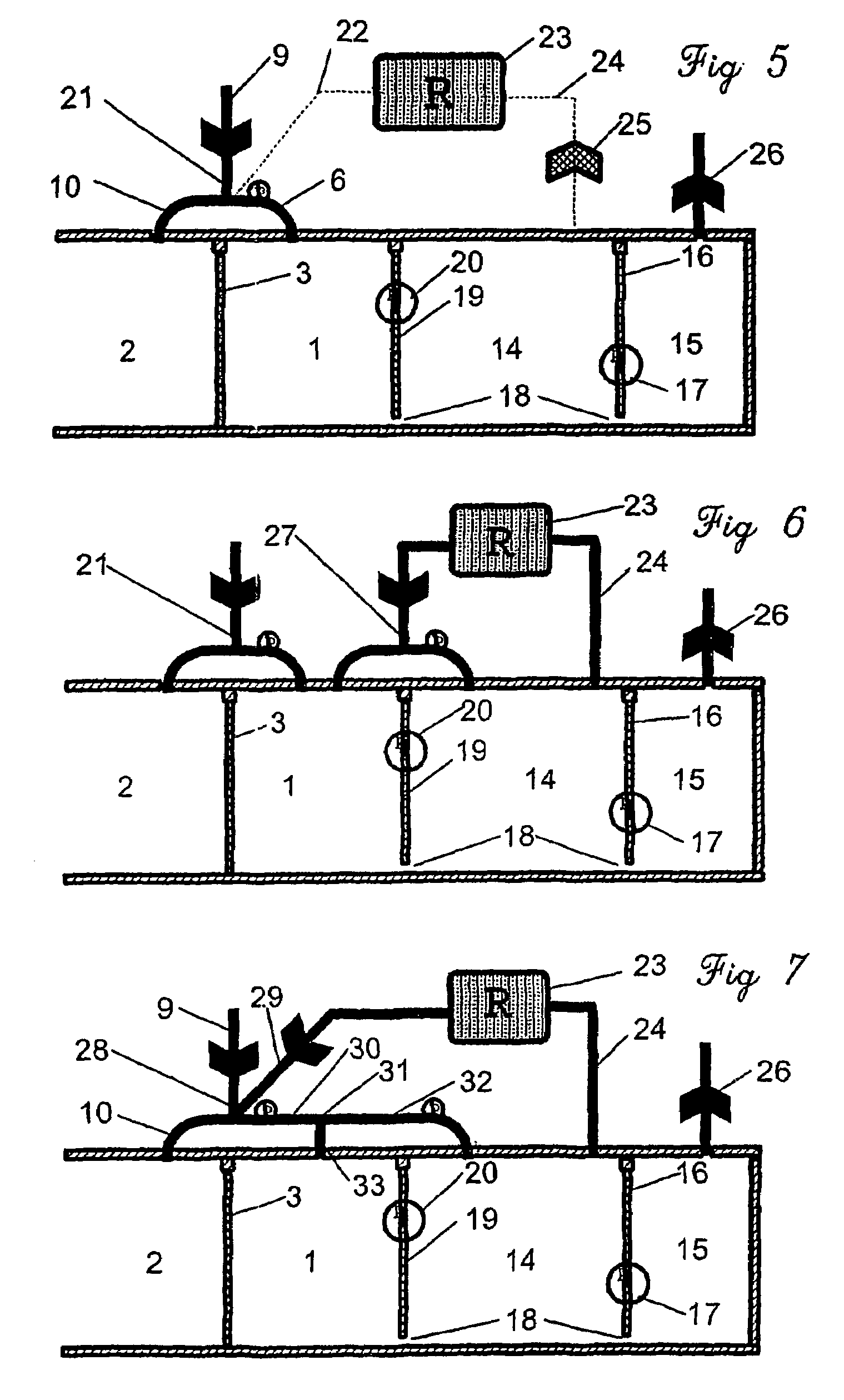
[0029]The centre of the invention is a device or an arrangement with minimum three connected channels / flow paths where air can flow alternative routes depending on local pressure ratio in connected rooms / cells / zones. In at least one airflow route 6 is an arrangement that functions in such a manner that airflow in 6 gives a certain drop in pressure. Such an arrangement will hereafter be known as a resistor element. The resistor element, for example in 6, can be any device giving a difference in pressure by airflow, such as a restriction in area, a frame grate, a filter, a device influenced by flow and / or pressure ratio in or in connection to 6, a device influenced by conditions connected to door(s) between rooms with channels connected to the invention or a combination of two or more of said possibilities or equivalent. The design or dimension of the airflow route may also constitute or be include...


PUM


Abstract

A device for controlling airflow between a clean room (1) and an adjacent room (2) is described. Channels (10, 6) lead from the rooms (1, 2) to a common junction (8). A ventilation channel (9) is leading from the common junction (8) for feeding or carrying off air. In the channel (10) from the clean room (1) is included a resistor element for the airflow, while the channel (6) from the adjacent room (2) has low hydraulic impedance.

Description

FIELD OF THE INVENTION[0001]The present invention relates to ventilation installations in buildings, where the building is divided into zones or rooms with differing air purities. In particular, the invention is applicable in the health sector, operating theatres, etc., and in the industry for clean rooms or in connection with particularly contaminated rooms. However, the invention is applicable in a number of other ventilation field where it is desirable to prevent or reduce the incorporation of air of particular content, or lack of particular content (pollen or other allergens, odours, dust, etc.), from one area to another, such as isolation wards and sterile rooms.STATE OF THE ART[0002]Fundamental for all forms of separation / isolation is separate rooms / cubicles / wards. With pollution entrained in the air, one tries to avoid air spreading from a polluted area to a cleaner one. Another general method is to dilute with clean air. The clean air can be fresh / treated air from outside, o...

Claims


Application Information

Patent Timeline
Patent Type & Authority Patents(United States)
IPC IPC(8): B01L1/04A61G13/00F24F3/16F24F11/00
CPCA61G13/108F24F3/161F24F11/0001F24F2011/0002F24F3/167
Inventor BJORDAL, ODDVAR INGE
Owner BJORDAL ODDVAR INGE
Why Eureka
Try Eureka