Bifurcated multicapsule intraluminal grafting system and method

a multi-capsule, intraluminal grafting technology, applied in the field of improved system and method for emplacing a prosthesis, can solve the problems of inability to conduct the lumen, significant life-threatening surgical repair, and large diameter of early prior art devices, and achieve enhanced ingrowth and sealing effect, improved grafting efficiency, and reduced the number of connecting points among the various members of the superior attachment.

Inactive Publication Date: 2006-10-10
LIFEPORT SCI
View PDF55 Cites 57 Cited by
  • Summary
  • Abstract
  • Description
  • Claims
  • Application Information

AI Technical Summary

Benefits of technology

[0012]The present system has several advantages over prior art systems. In particular, the present system incorporates various novel structural features which enhance the efficiency of the system as well as facilitates the effective deployment of the prosthesis within a vessel or body lumen. Moreover, the present system embodies a design which is optimized for ease of operation and manufacturability. Additionally, the prosthesis includes various advancements which also enhance the overall effectiveness of the system.
[0014]The new and improved distal or superior capsule assembly includes a superior end configured with a nose cone for improved maneuverability of the intraluminal delivery system within vessels or corporeal lumens, as well as for providing a gradual transition of the overall profile of the delivery system. The control wire assembly also includes a handle having a more manufacturable single piece design and embodies a rack and pinion device which is configured coaxially with the control wire for more precise control.
[0015]The lock wire assembly is provided with an ipsilateral lock spaced-apart from a pusher button which can be manipulated such that a limb of the prosthesis can be deployed in tension or compression. Also, the inferior end of the locking wire assembly includes a handle shaped so that it can be manipulated more conveniently. The pull wire assembly includes a slidable pusher button and a lock which cooperate in order to provide the system with the capability of deploying another prosthesis limb in tension or compression. The guiding tube assembly also includes additional marking bands for providing an enhanced view of the guiding tube assembly under fluoroscopy. The guiding tube assembly also includes non-radiopaque marker bands for conveniently identifying the chronological sequence in which portions of the guiding tube assembly are removed during the deployment process.
[0017]The improved prosthesis includes additional radiopaque members positioned along its length for the purpose of better identifying the configuration of the prosthesis under fluoroscopy. The improved prothesis also includes additional means for insuring an enhanced ingrowth and sealing effect within the vessel or corporeal lumen. Furthermore, the superior end of the prosthesis is provided with a superior attachment system embodying V-shaped members with hooked terminal ends which cooperate with a generally sinusoided frame to seat the superior end of the prosthesis within a vessel or lumen. This improved attachment system is optimally configured to be effective even in harsh environments wherein significant stresses are placed upon the members comprising the attachment system. Significantly, the number of connecting points among the various members of the superior attachment have been minimized.

Problems solved by technology

For example, various types of aneurysms or other deteriorative diseases may affect the ability of the lumen to conduct fluids and in turn may be life-threatening.
For repair of vital vessels such as the aorta, surgical repair is significantly life-threatening.
The early prior art devices were large in diameter, mechanically complex and in turn were susceptible to mechanical failure.
Similarly, the prior art systems were configured in such a way that the graft was relatively difficult to deploy in the correct position.
Further, the prior prostheses were sometimes ill suited to withstand the high pressures existing in the vessels and, consequently, experienced structural failures.

Method used


Image

  • Bifurcated multicapsule intraluminal grafting system and method
  • Bifurcated multicapsule intraluminal grafting system and method
  • Bifurcated multicapsule intraluminal grafting system and method

Examples


Embodiment Construction

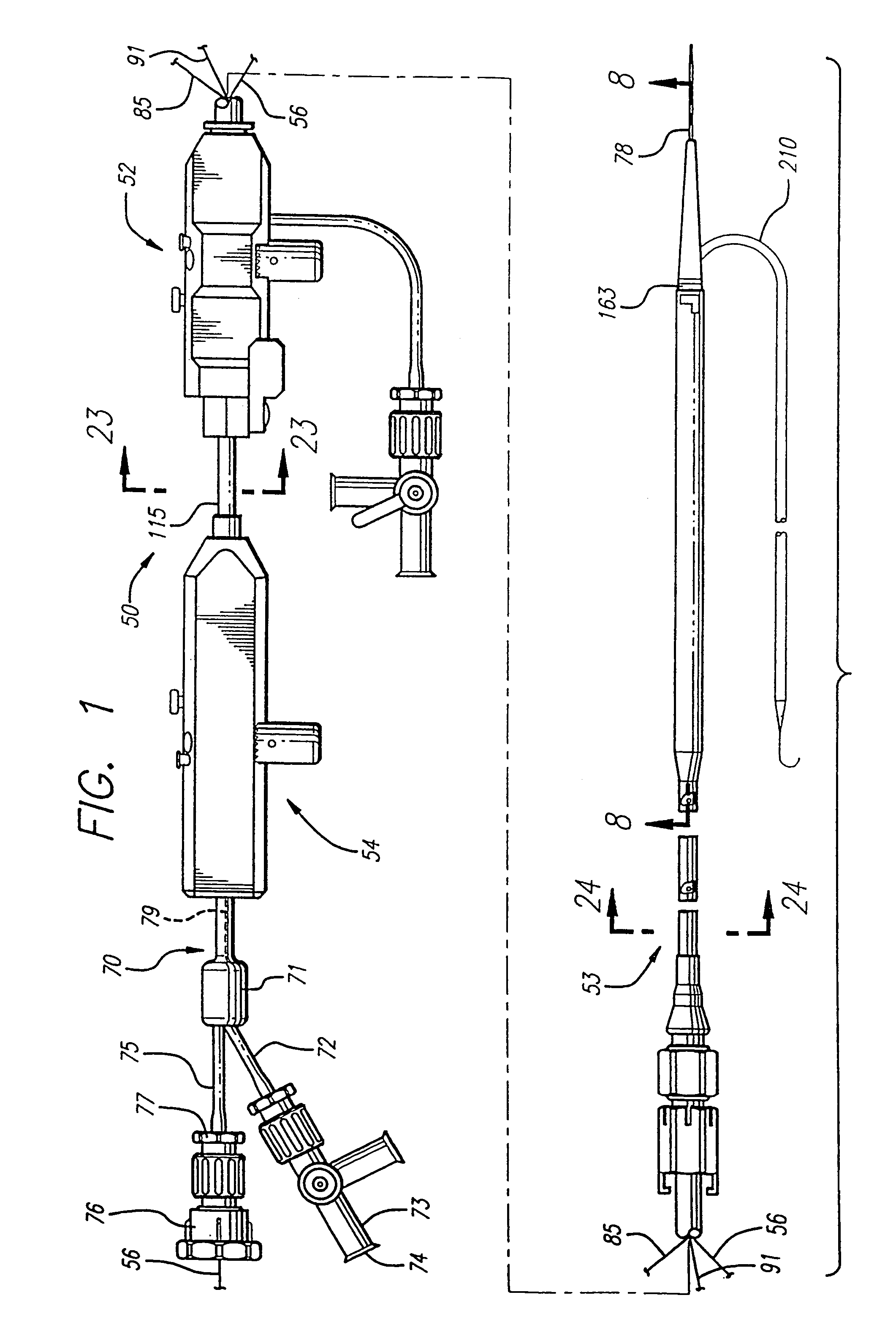
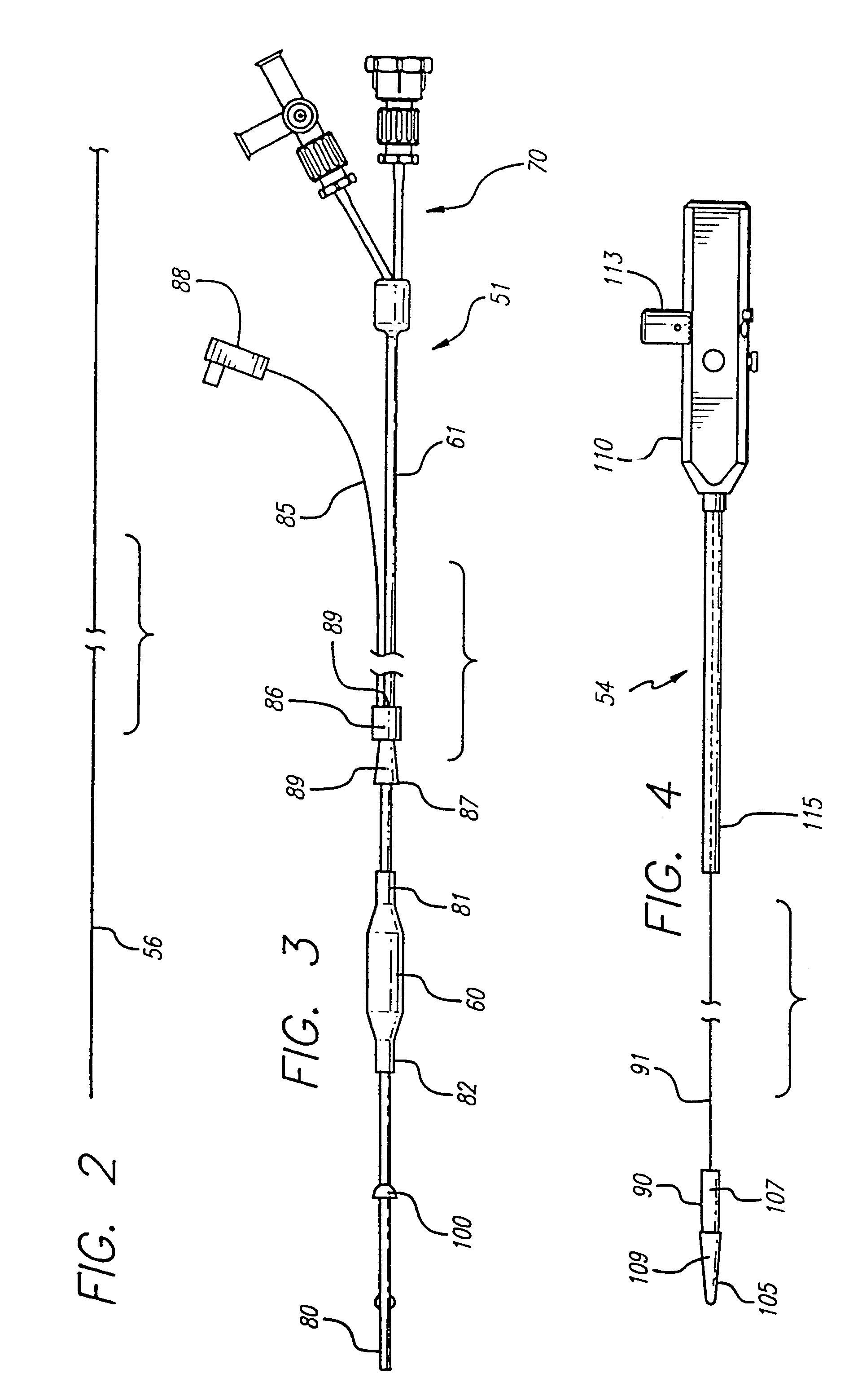
[0055]As shown in the drawings and for purposes of illustration, the invention is embodied in an intraluminal grafting system of the type having a balloon catheter assembly, an ipsilateral capsule catheter assembly, contralateral and distal capsule assemblies and means interacting therewith, and a protective sleeve or capsule jacket. The novel features of the present system are directed towards enhancing the efficiency of the intraluminal grafting system, facilitating the effective deployment of a prosthesis within a vessel or body lumen and providing a prosthesis well suited for effectively repairing the vessel or lumen.

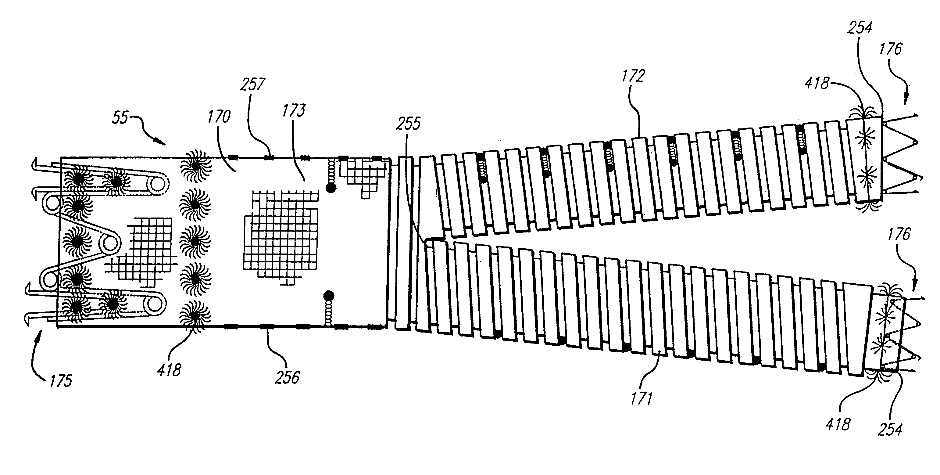
[0056]In the present system, the prosthesis or graft is comprised of a bifurcated tubular body having superior and inferior extremities. The superior extremity of the graft comprises a main tubular member which bifurcates into two tubular legs which comprise the inferior extremity of the graft. For clarity, the two tubular legs are referred to herein as the ipsilate...


PUM


Abstract

An apparatus for repairing a vessel using a multicapsule catheter having first, second and third capsules for releasably retaining each terminal end of a bifurcated graft. The method for repairing the vessel includes the steps of performing a surgical technique to gain remote access to the vessel, advancing the multicapsule catheter within the vessel and releasing the bifurcated graft within the vessel to thereby repair the vessel.

Description

CROSS-REFERENCES TO RELATED APPLICATIONS[0001]This application is a continuation of Ser. No.09 / 864,822, filed May 22, 2001, now U.S. Pat. No. 6,663,666, which is a continuation of Ser. No. 09 / 484,285 filed Jan. 18, 2000, now U.S. Pat. No. 6,235,050, which is a continuation of application Ser. No. 08 / 996,330, filed Dec. 22, 1997, now U.S. Pat. No. 6,039,758, which is a continuation of application Ser. No. 08 / 707,179, filed Sep. 3, 1996 now U.S. Pat. No. 5,824,044, which is a continuation-in-part of application Ser. No. 08 / 241,476, filed May 12, 1994, now U.S. Pat. No. 5,628,783.BACKGROUND OF THE INVENTION[0002]This invention relates to an improved system and method for emplacing a prosthesis and, more particularly, to a delivery catheter and method of use for placement within a corporeal lumen of a bifurcated graft having attachment systems.[0003]It is well established that various fluid conducting body or corporeal lumens, such as veins and arteries, may deteriorate or suffer trauma...

Claims


Application Information

Patent Timeline
Patent Type & Authority Patents(United States)
IPC IPC(8): A61F2/06A61B17/00A61B17/11A61B19/00A61F2/00A61F2/88A61F11/00A61M25/12
CPCA61F2/07A61F2/954A61F2/958A61B19/54A61F2/88A61F2002/065A61F2002/075A61F2002/8483A61F2002/8486A61F2002/9517A61F2250/0098A61F2/89A61B90/39A61F2/9517
Inventor QUIACHON, DINAH B.PIPLANI, ALEC A.BAKER, STEVE G.WILLIAMS, RONALD G.WILLIAMS, RICHARD S.OSBORN, KENNETH L.LAYMAN, TED W.JOHANSSON, PETER K.
Owner LIFEPORT SCI
Why Eureka
Try Eureka