
Remote server object architecture for speech recognition

a speech recognition and object technology, applied in the field of speech recognition object architecture, can solve problems such as much more difficult processing, and achieve the effect of enhancing performance and maintenan

Inactive Publication Date: 2006-10-10
ELIZA
View PDF43 Cites 23 Cited by
  • Summary
  • Abstract
  • Description
  • Claims
  • Application Information

AI Technical Summary

Benefits of technology

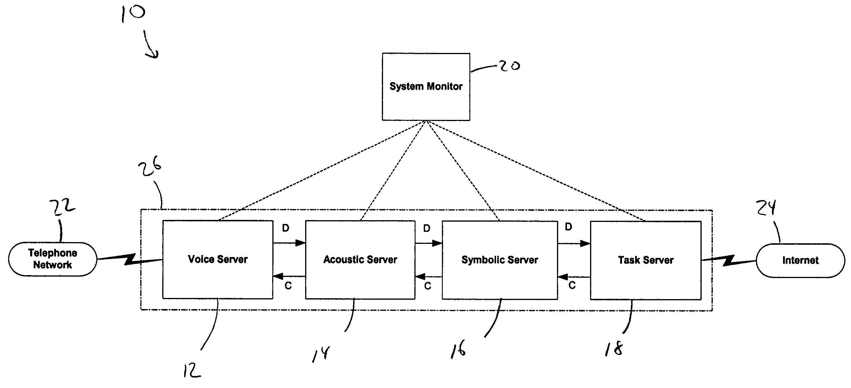
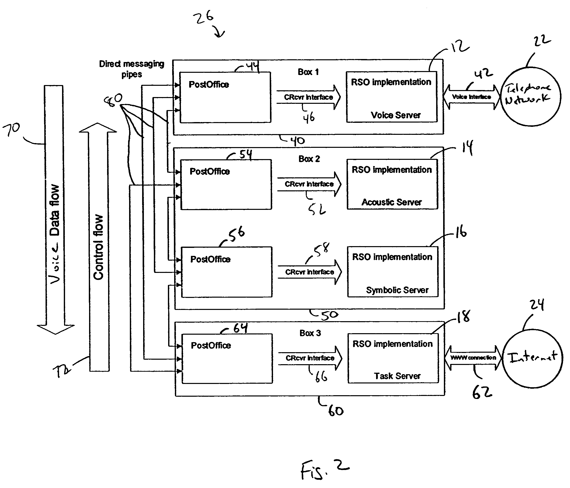
[0010]The present invention is directed to implementation of computing-intensive speech recognition systems that require simultaneous operations of multiple functional units. This is accomplished by having a number of discrete servers which can be located in separate computer systems. Four types of functions related to speech recognition have been identified and isolated in different operating units. Performance and maintenance is enhanced by having a unidirectional data pipeline, from one server to another, while control flow streams in the opposite direction.
[0011]The configuration of the system provides the ability to separate and encapsulate the modular high-level functions associated with each server, which are controlled by a central monitoring system. Consequently, the system is capable of enabling changes to transactions and maintenance on the system without shutting down the entire system and is able to compensate for malfunctions in any one or more of the components of the system without affecting the operation of the entire system. System-wide load balancing is made possible by means of borrowing functional servers from the applications having low load and reassigning them to more demanding applications.

Problems solved by technology

In continuous speech systems, however, this process is much more difficult, since there typically are no breaks between words in the acoustic stream.

Method used


Image

  • Remote server object architecture for speech recognition
  • Remote server object architecture for speech recognition
  • Remote server object architecture for speech recognition

Examples


Embodiment Construction

[0030]The present invention is directed to a speech recognition system which can be used to conduct automated telephone transactions. In general, the system receives an application over either a local network or the internet from a party conducting the transaction. The application contains the code that operates the transaction. The transaction prompts are presented to the respondent over a telephone network, and the replies are received by the speech recognition system spoken by the respondent. The voice data that represent the answers given by the respondent are broken down into a phonetic stream of data which can be recognized by the system. The system converts the phonetic stream of data into a word list or syntactic data message which is then converted to a semantic representation of the spoken answers given by the respondent. The semantic representation can then be transmitted to a transaction initiator over the local network or the internet.

[0031]FIG. 1 is a schematic block d...


PUM


Abstract

A speech recognition system includes a line of service including a first server object coupled to a telephone network for receiving a voice data message from the telephone network, a second server object having a first connection to the first server object for receiving the voice data message from the first server object and converting the voice data message to a phonetic data message, a third server object having a second connection to the second server object for receiving the phonetic data message from the second server object and converting the phonetic data message to a syntactic data message and a fourth server object having a third connection to the third server object for receiving the syntactic data message from the third server object and converting the syntactic data message to a semantic data message, which is representative of the voice data message. The first, second, third and fourth server objects may be remote with respect to each other and the first, second and third connections are formed over a first computer network.

Description

CROSS REFERENCES TO RELATED APPLICATIONS[0001]This application claims the benefit of priority from commonly owned U.S. Provisional Patent Application Ser. No. 60 / 192,091, filed Mar. 24, 2000, entitled COMBINED SYNTACTIC AND SEMANTIC SEARCH, PARSING, AND APPLICATION ACCESS; U.S. Provisional Patent Application Ser. No. 60 / 191,915, filed Mar. 24, 2000, entitled SPEECH RECOGNITION APPLICATION TECHNOLOGY USING WEB, SCRIPTING AND SEMANTIC OBJECTS; U.S. Provisional Patent Application Ser. No. 60 / 192,090, filed Mar. 24, 2000, entitled A NOVEL APPROACH TO SPEECH RECOGNITION; and U.S. Provisional Patent Application Ser. No. 60 / 192,076, filed Mar. 24, 2000, entitled REMOTE SERVER OBJECT ARCHITECTURE FOR SPEECH RECOGNITION.[0002]This application is also related to the following copending U.S. patent applications, the contents of which are incorporated herein in their entirety by reference:[0003]“A Novel Approach To Speech Recognition,” U.S. patent application Ser. No. 09 / 815,768;[0004]“Phonetic...

Claims


Application Information

Patent Timeline
Patent Type & Authority Patents(United States)
IPC IPC(8): G10L11/00G06F15/16G10L15/18H04M1/64G06F17/27G06Q30/00G10L15/00G10L15/02G10L15/14G10L15/28
CPCG06F17/271G06F17/274G06F17/2785G06Q30/02G10L15/02G10L15/1822G10L15/30G10L15/14G10L15/1815G10L15/193G10L2015/025G06F40/211G06F40/253G06F40/30
Inventor BOULANOV, OLEG
Owner ELIZA
Learn More