System and method for evaluation of electric characteristics of printed-circuit boards

Inactive Publication Date: 2006-10-10
NEC CORP
View PDF18 Cites 13 Cited by
  • Summary
  • Abstract
  • Description
  • Claims
  • Application Information

AI Technical Summary

Benefits of technology

[0029]It is an object of the invention to provide a system and method for evaluation of electric characteristics of printed-circuit boards in which evaluation is made as to whether the printed-circuit boards are designed to suppress variations of power voltages while avoiding radiation of unwanted electromagnetic waves due to resonance of power supply circuits inside of active components installed on the printed-circuit boards.

Problems solved by technology

Such voltage waveshape cannot guarantee a normal operation of a subject circuit which is a subject being evaluated.
Hence, it can be said that a printed-circuit board having such a subject circuit is inappropriate for manufacturing.
Until now, however, no engineers actually propose techniques for evaluation of the high frequency characteristics of the power supply circuit by numerical analysis.
As a result, the engineers related to technologies of printed-circuit boards suffer from problems, as follows:(1) It is impossible to sufficiently guarantee quality in circuit operations of the printed-circuit boards.(2) The printed-circuit boards radiate unwanted electromagnetic waves.
For this reason, it becomes difficult to supply the active component with stable DC voltage.
That is, it is hard to guarantee stable operations of the active component.
If the circuits are designed not to reduce the inductance so much, variations of power voltage become large, so it may be impossible to guarantee normal circuit operations.
This causes variations of power voltage to become large.
In that case, it becomes hard to pass regulations specified by standards regarding EMI (i.e., electromagnetic interference) or radiation of unwanted electromagnetic waves.

Method used


Image

  • System and method for evaluation of electric characteristics of printed-circuit boards
  • System and method for evaluation of electric characteristics of printed-circuit boards
  • System and method for evaluation of electric characteristics of printed-circuit boards

Examples


embodiment 1

[A] EMBODIMENT 1

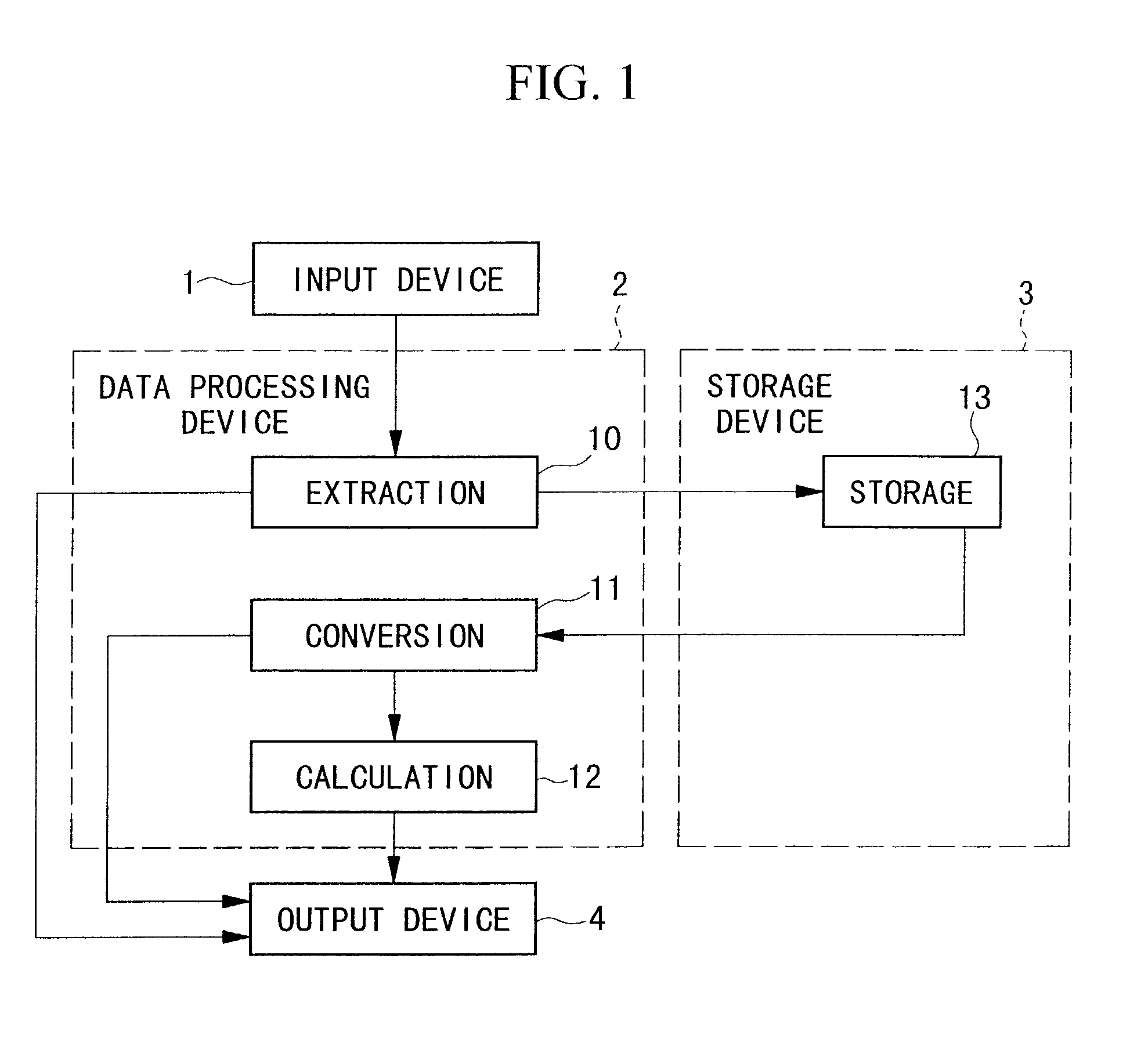
[0074]FIG. 1 is a block diagram showing a configuration of a printed-circuit board characteristic evaluation system in accordance with embodiment 1 of the invention.

[0075]The printed-circuit board characteristic evaluation system of FIG. 1 is mainly configured by an input device 1, a data processing device 2, a storage device 3 and an output device 4. Herein, the data processing device 2 contains an extraction block 10, a conversion block 11 and a calculation block 12. In addition, the storage device 3 contains a storage block 13.

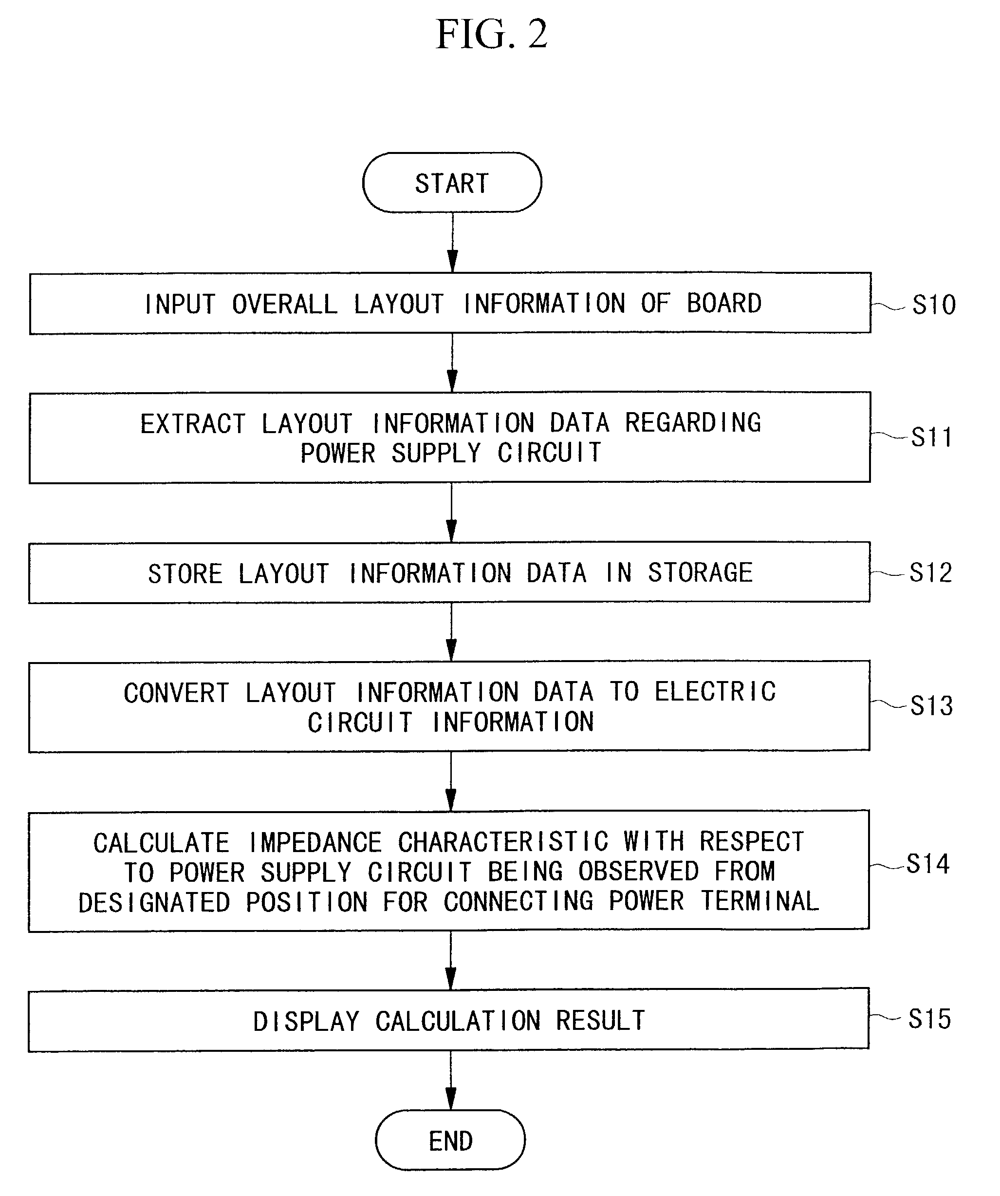
[0076]Next, operations of the printed-circuit board characteristic evaluation system will be described in detail with reference to FIG. 2 and FIGS. 3A, 3B. Herein, FIG. 2 is a flowchart showing overall operations of the present system, while FIGS. 3A, 3B show an example of a configuration of a four-layer printed-circuit board “20”, which is a subject being evaluated. Specifically, FIG. 3A is a plan view of the board, and FIG. 3B is a section...

embodiment 2

[B] EMBODIMENT 2

[0095]FIG. 6 is a block diagram showing a configuration of a printed-circuit board characteristic evaluation system in accordance with embodiment 2 of the invention.

[0096]As compared with the aforementioned embodiment 1 shown in FIG. 1, the embodiment 2 of FIG. 6 is characterized by additionally incorporating a comparison block 14 in the data processing device 2. This comparison block 14 brings a capability in making a decision as to whether resonance is caused to occur in the power supply circuit or not.

[0097]Next, operations of the present embodiment will be described with reference to a flowchart of FIG. 7.

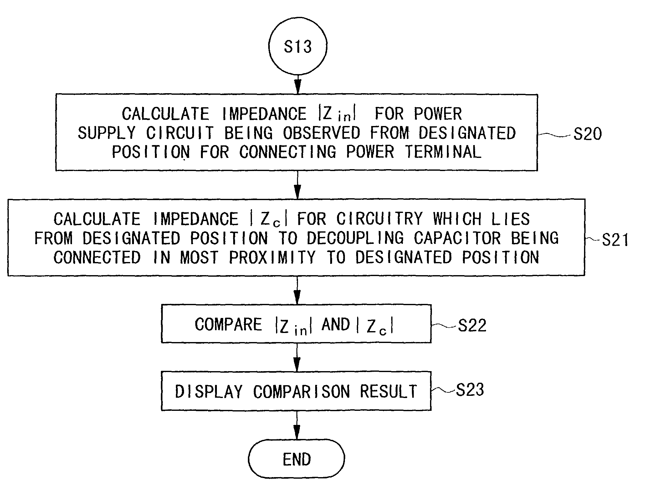
[0098]The present embodiment uses the aforementioned steps S10 to S13 shown in FIG. 2. Hence, those steps are omitted in FIG. 7. That is, the present embodiment is characterized by performing steps S20 to S23 after the aforementioned steps S10 to S13.

[0099]In the aforementioned step S13, the present system produces the electric circuit information with respect t...

embodiment 3

[C] EMBODIMENT 3

[0114]FIG. 18 is a block diagram showing a configuration of a printed-circuit board characteristic evaluation system in accordance with embodiment 3 of the invention.

[0115]As compared with the aforementioned system of the embodiment 2 shown in FIG. 6, the present system of the embodiment 3 is characterized by further incorporating a layout change block 15 and a secondary storage block 16, which are respectively installed in the data processing device 2 and the storage device 3. Using the layout change block 15, it is possible to change overall layout information of the board. The present embodiment uses the layout change block 15 mainly for changing a layout of the power supply circuit. The secondary storage block 16 stores a program and data regarding a resonance suppression technique for suppressing resonance of the power supply circuit in advance.

[0116]Next, operations of the present system will be described with reference to a flowchart of FIG. 19.

[0117]Overall o...


PUM


Abstract

A printed-circuit board characteristic evaluation system is basically configured by an input device, a data processing device, a storage device and an output device. Herein, the input device inputs layout information representing an overall layout of a printed-circuit board installing at least one active component, from which layout information data regarding a power supply circuit is extracted and is stored in the storage device. The layout information data is converted to electric circuit information representing an equivalent circuit model with respect to a selected side of the printed-circuit board. Then, calculations are performed based on the layout information data to produce impedance characteristics with respect to the power supply circuit. A decision is made as to whether resonance is caused to occur in the power supply circuit on the basis of results of comparison of the impedance characteristics. The output device outputs the impedance characteristics as well as resonance information. If it is determined that resonance is caused to occur in the power supply circuit, the system changes the layout information, from which new layout information data is being extracted. In addition, a resonance suppression technique (e.g., installation of a decoupling capacitor) is applied to a certain point of the power supply circuit or a prescribed power terminal connecting position. Thus, the system is capable of performing evaluation as to whether printed-circuit boards are well designed to suppress variations of power voltages while inhibiting radiation of unwanted electromagnetic waves from occurring due to resonance of power supply circuits.

Description

[0001]This application is a division of U.S. patent application Ser. No. 09 / 551,838, filed Apr. 18, 2000 now U.S. Pat. No. 6,546,528, which claims benefit of priority of Japanese Patent Application 11-114200, filed Apr. 21, 1999.BACKGROUND OF THE INVENTION[0002]1. Field of the Invention[0003]This invention relates to systems and methods that perform evaluation on electric characteristics of printed-circuit boards in accordance with numerical analysis. In addition, this invention also relates to storage media storing programs and data that actualize evaluation of the electric characteristics of the printed-circuit boards.[0004]This application is based on Patent Application No. Hei 11-114200 filed in Japan, the content of which is incorporated herein by reference.[0005]2. Description of the Related Art[0006]Conventionally, engineers propose a variety of techniques that perform evaluation using numerical analysis as to whether printed-circuit boards operate normally or not. One of tho...

Claims


Application Information

Patent Timeline
IPC IPC(8): G06F17/50H05K3/00H05K1/02
CPCG06F17/5036H05K1/0231H05K3/0005G06F30/367
Inventor SASAKI, HIDEKIHARADA, TAKASHI
Owner NEC CORP
Why Eureka
Try Eureka