
Hydraulastic recoil pad for a shoulder firearm

a recoil pad and hydroulastic technology, applied in the field of firearms, can solve the problems of limiting the effectiveness of the recoil reducer apparatus, affecting the performance of the recoil reducer, and the insensitivity of the shooter to certain factors, so as to improve the performance of a given pad deflection, reduce the number of components, and facilitate manufacturing

Active Publication Date: 2006-10-17
ENIDINE
View PDF15 Cites 20 Cited by
  • Summary
  • Abstract
  • Description
  • Claims
  • Application Information

AI Technical Summary

Benefits of technology

"The present invention provides a recoil pad for shoulder firearms that can absorb energy and reduce the impact or recoil force felt by the shooter. The recoil pad is easy to manufacture and can be integrated into the stock of the firearm. It includes a piston assembly with a hydraulic element and an elastomeric element to effectively absorb the recoil energy. The recoil pad can be used with a wide range of ammunitions and provides improved performance compared to prior art devices. It is also cost-effective and easy to manufacture."

Problems solved by technology

The amount of resulting force that is felt by the shooter is jarring and is often uncomfortable, and to that end there have been numerous attempts that have been made in the field to devise a recoil reducing apparatus in an effort to dissipate the recoil force, rather than to have the shooter receive a sharp blow to the shoulder.
A fundamental problem found in hydraulic type recoil reducing apparatus, such as described by Ahearn, is their insensitivity to certain factors, such as the type of ammunition used and the weight of the firearm itself.
Each of the preceding factors contribute to the recoil characteristics of the firearm and therefore may limit the effectiveness of the recoil reducer apparatus.
These devices, however, are able to provide only a fractional amount of energy absorption and are therefore only moderately effective.

Method used


Image

  • Hydraulastic recoil pad for a shoulder firearm
  • Hydraulastic recoil pad for a shoulder firearm
  • Hydraulastic recoil pad for a shoulder firearm

Examples


first embodiment

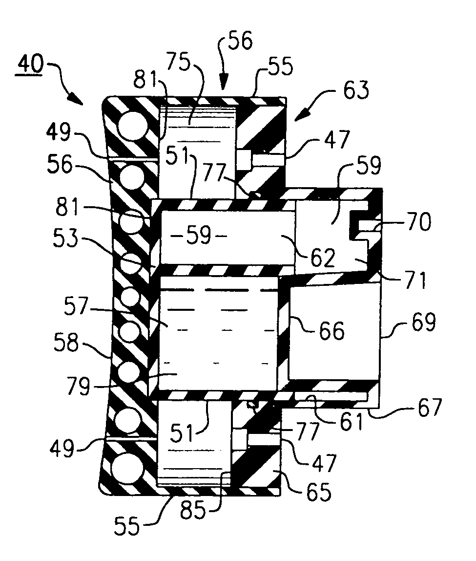
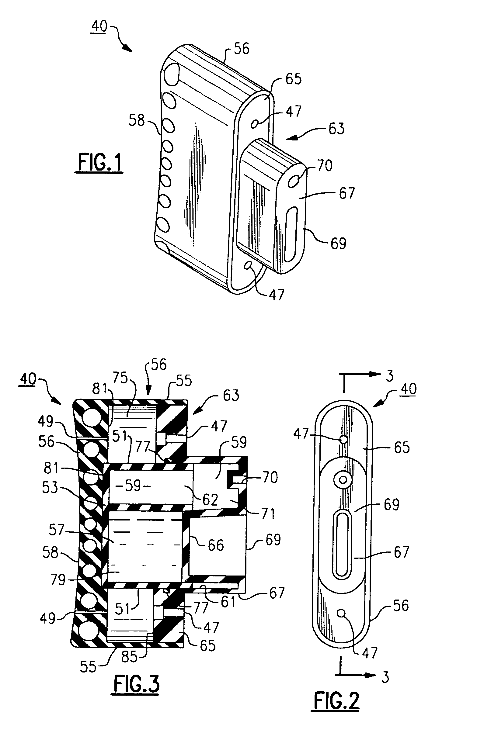
[0031]Referring to FIGS. 1–3, there is shown a hydraulastic recoil pad 40 that is made in accordance with the present invention. The pad 40 includes an elastomeric pad enclosure 56, made from an elastomer, including a proximal end side 58 which is preferably reinforced and shaped to conform to the shoulder of the shooter. An extending portion 55 of the elastomeric pad enclosure 56 is used to cover the remainder of the herein described apparatus, the pad enclosure including an interior cavity sized to receive a fitted chamber assembly 53 against a distal facing wall surface 81 of the reinforced proximal end side 58 thereof.

[0032]The chamber assembly 53 is preferably a plastic molded unitary component, including a pair of adjacent chambers, namely a first chamber 57 and an adjacent second chamber 59. Each of the first and second chambers 57, 59 are defined by side walls 51 defining each respective chamber, as well as a single open end 61, 62, each open end facing the distal side of th...

third embodiment

[0041]Referring to FIGS. 6–9, a hydraulastic recoil pad made in accordance with the present invention is herein described. The recoil pad 160, according to this embodiment, includes a body portion 164 defined by a substantially cylindrical shaped section, made preferably from a moldable plastic or another suitable material such as aluminum, the body portion having a formed interior cavity 168. The body portion 164 further includes an interior end wall 172 on a distal side 176 thereof wherein for purposes of this discussion, the “distal” side as referred to herein is that side of the recoil pad 160 which is attached to the rifle stock as opposed to the proximal side, the side which is adjacent to the shoulder of the shooter. The interior end wall 172 includes a pair of spaced through openings 180 which act as bearings for the piston rods 206, as well as a distal projecting portion 184.

[0042]A piston assembly 188 comprises a piston head 192, which according to this embodiment, is a di...


PUM


Abstract

A recoil pad for a shoulder firearm includes at least one piston member that is caused to move axially from an initial axial position to a second axial position upon application of the recoil force from the firearm. The axial movement of the piston member causes fluid movement within a column relative to a variable or fixed orifice area wherein the fluid movement causes resistance that absorbs the energy. A mechanical and / or hydraulic and / or elastomeric feature returns the piston to the initial axial position upon cessation of the applied recoiling force.

Description

FIELD OF THE INVENTION[0001]This invention relates to the field of firearms, and more particularly to an improved recoil force reduction apparatus for a shoulder firearm, such as a rifle or shotgun, the apparatus including a combination of hydraulic and elastomeric features.BACKGROUND OF THE INVENTION[0002]It is commonly well known that shoulder firearms, such as rifles and shotguns, recoil suddenly and violently in a rearward direction when the firearm is discharged. The amount of resulting force that is felt by the shooter is jarring and is often uncomfortable, and to that end there have been numerous attempts that have been made in the field to devise a recoil reducing apparatus in an effort to dissipate the recoil force, rather than to have the shooter receive a sharp blow to the shoulder.[0003]The types of recoil reducing apparatus that are presently known have included numerous mechanical and / or pneumatic systems and hydraulic type devices. For example, Ahearn, U.S. Pat. No. 3...

Claims


Application Information

Patent Timeline
Patent Type & Authority Patents(United States)
IPC IPC(8): F41A21/00
CPCF41C23/08
Inventor DAUL, TERRANCE E.KELLY, JEFFREY T.RADICE, DANIEL C.BUCHOLTZ, BRIAN C.MILLER, THOMAS J.
Owner ENIDINE
Learn More