Air deflector

a technology of air deflector and air filter, which is applied in the direction of roofs, transportation and packaging, vehicle arrangements, etc., can solve the problems of increasing air resistance and inferiority of vehicle aerodynamic performance, and achieve the effect of improving vehicle aerodynamic performan

Inactive Publication Date: 2006-10-17
ISUZU MOTORS LTD
View PDF16 Cites 28 Cited by
  • Summary
  • Abstract
  • Description
  • Claims
  • Application Information

AI Technical Summary

Benefits of technology

[0007]It is therefore an object of the present invention to provide an air deflector which can ensure visibility of the marker lamps and which can prevent the flow of air from impinging on the upper corner areas of the vertical front face of the van body, thereby improving the aerodynamic performance of the vehicle.
[0008]The object is accomplished by an air deflector, which is attached to a vehicle provided with a cab and a van body in a form of box and which is mounted on a roof of the cab so as to improve an aerodynamic performance of the vehicle, comprising;
[0011]Provision of the marker lamp on the air deflector allows the upper corner areas of the front face of the van body to be covered with the air deflector, and therefore, these corner areas can be shielded with the air deflector against the flow of air during driving. The flow of air regulated by the air deflector is directed to the rear of the vehicle without impinging on the corner areas of the front face of the van body, whereby the aerodynamic performance of the vehicle is improved.
[0012]Preferably, an upper surface of the marker lamp is formed to be substantially flush with the upper face of the air deflector, so that a continuous upper surface of the air deflector is formed; a side surface of the marker lamp is formed to be substantially flush with the side face of the air deflector, so that a continuous side surface of the air deflector is formed; and a ridge portion joining the upper and side surfaces of the marker lamp is substantially in alignment with the ridge portion of the air deflector, so that a continuous ridge is formed. Since the upper surface, side surface and ridge portion of the marker lamp are substantially flush or aligned with the upper surface, side surface and ridge portion of the air deflector respectively, the flush surface configuration overall the air deflector can be ensured, and therefore, the marker lamp can be installed on the air deflector without deteriorating the performance of the air deflector regulating the airflow and reducing the air resistance. More preferably, the upper and side surfaces of the marker lamp are configured to enlarge rearward along the ridge portion of the air deflector.

Problems solved by technology

This results in increase of the air resistance and inferiority of the aerodynamic performance of the vehicle.

Method used


Image

  • Air deflector
  • Air deflector
  • Air deflector

Examples


Embodiment Construction

[0025]With reference to the attached drawings, a preferred embodiment of the present invention is described hereinafter.

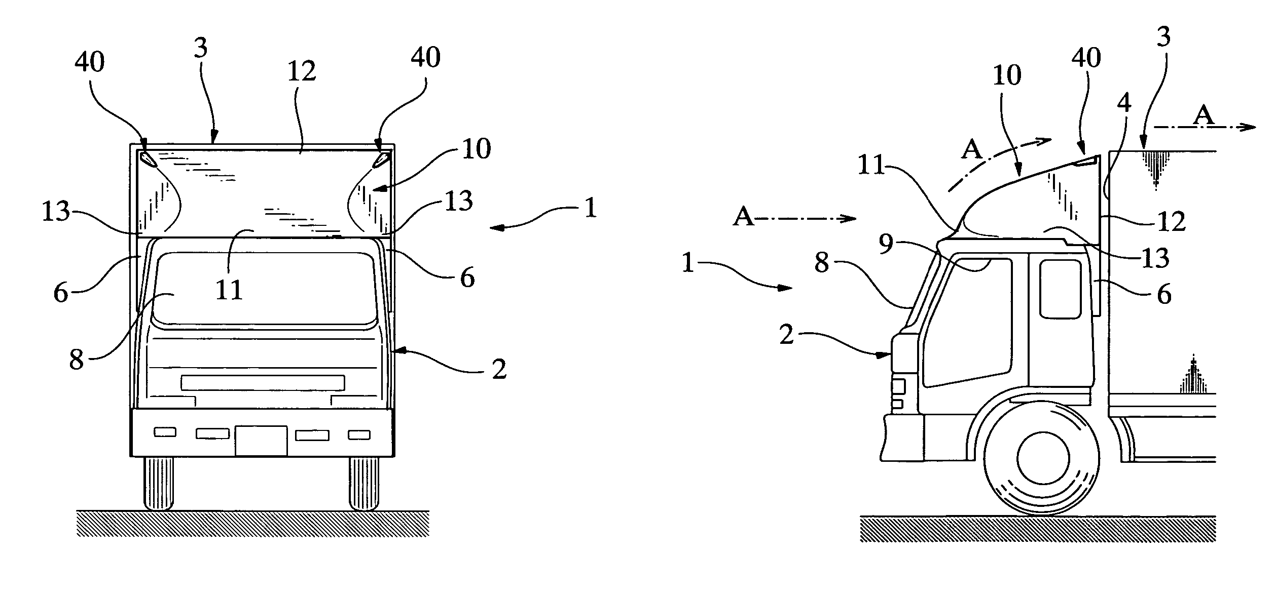
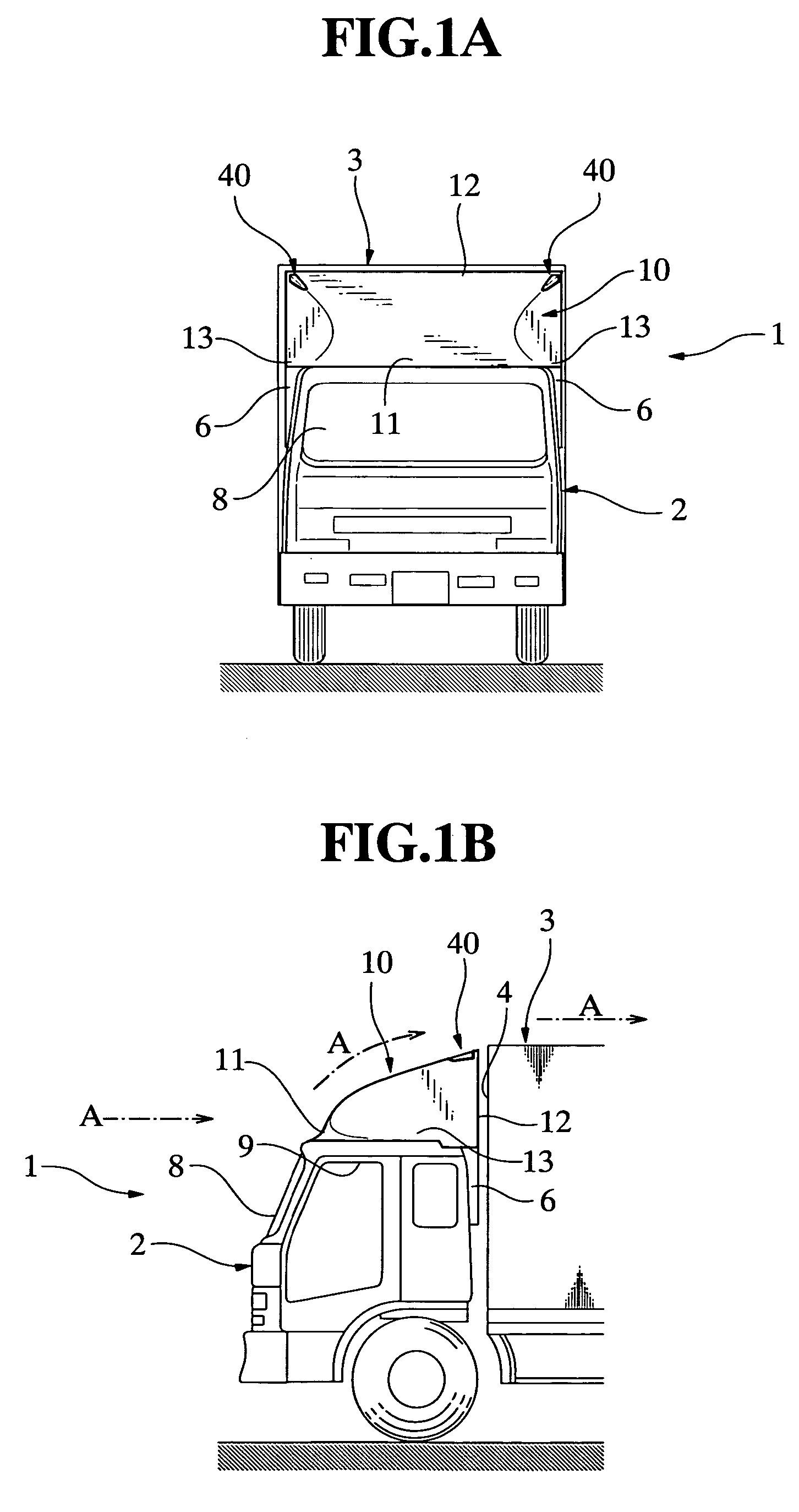
[0026]FIGS. 1A and 1B are a front elevational view and a partial side elevational view generally illustrating an arrangement of a relatively large-sized cab-over-engine truck provided with an air deflector according to the present invention.

[0027]The vehicle 1 as shown in FIGS. 1A and 1B is a cab-over-engine truck which comprises a cab or cabin 2 and a van body 3. An internal combustion engine (not shown) is located beneath the cab 2, and the van body 3 is carried by a chassis frame. An air deflector 10 is attached to a roof panel of the cab 2 so that the whole roof of the cab 2 is covered with the air deflector 10.

[0028]A front edge portion 11 of the air deflector 10 is positioned on an upper frame portion of a front-windshield 8. Side edge portions 13 of the air deflector 10 extend rearward along upper frame portions of openings 9 for outwardly swinging doors (no...


PUM


Abstract

An air deflector (10) is attached to a roof of a cab (2). A rear edge portion (12) of the air deflector has a configuration identical with an upper part of a vertical front face (4) of a van body (3) or a configuration closely resembling the upper part thereof, as viewed from the front. A marker lamp (40) is located on a ridge portion (32) of the air deflector in proximity to the rear edge portion. An upper surface (41) and a side surface (43) of the marker lamp are formed to continue an upper face (31) and a side face (33) of the air deflector, and a ridge portion (42) of the marker lamp is in alignment with the ridge portion of the air deflector. The air deflector can ensure visibility of the marker lamps, while preventing the flow of air from impinging on the upper corner areas of the front face of the van body, whereby the aerodynamic performance of the vehicle is improved.

Description

FIELD OF THE INVENTION[0001]The present invention relates to an air deflector for a vehicle, and more specifically, to such an air deflector which can eliminate a stepped formation between a cab and a van body of a cab-over-engine truck for reduction of air resistance acting on the vehicle during driving.BACKGROUND OF THE INVENTION[0002]A cab style of a cab-over-engine truck affects automobile performances, such as a fuel consumption ratio. From an aspect of improvement of aerodynamic characteristics in a driving condition of the vehicle, various kinds of researches or studies have been carried out for long years, with respect to configurations of cabs or flush surface contours of vehicle bodies for reducing the air resistance, devices for reducing the air resistance, or the like. An excessively angled or inclined front-windshield results in reduction of an internal space of the cab, and therefore, in this kind of researches or studies, attempts have been made to improve the aerodyn...

Claims


Application Information

Patent Timeline
Patent Type & Authority Patents(United States)
IPC IPC(8): B62D35/00B60Q1/00B60Q1/28B60Q1/32
CPCB60Q1/32B62D35/001
Inventor KAWAI, KAZUO
Owner ISUZU MOTORS LTD
Why Eureka
Try Eureka