Connector

a technology of connecting rods and contacts, applied in the field of connecting rods, can solve the problems of imposing a further limit on the attempt to reduce limiting the size of the connector or and difficulty in achieving a pitch less than 0.2, so as to achieve the effect of increasing the density of the contacts and reducing the siz

Inactive Publication Date: 2006-10-17
FUJITSU COMPONENENT LTD
View PDF16 Cites 54 Cited by
  • Summary
  • Abstract
  • Description
  • Claims
  • Application Information

AI Technical Summary

Benefits of technology

[0033]According to the above invention, the contact module is formed into a sheet structure using a sheet with a predetermined thickness as a base foundation. Thereby, the above contact module is provided with flexibility and a desired configuration according to the usage mode of the connector can be realized upon implementing the contact module to the connector main body.
[0034]Also, since the contact can be formed into a thin sheet and a large number of contacts can be intricately arranged at a narrow pitch, the size of the connector can be reduced and the density of the contacts can be increased.
[0035]Additionally, by using the connector according to the present invention for connecting two substrates, the size of the connector can be reduced compared to the case in which the conventional two-piece type connector is used, and the problem of noise being generated at the connecting portion of the two connectors of the conventional two-piece connector can be resolved.

Problems solved by technology

However, since the conventional connector has contacts that are pin-shaped, it can be rightly assumed that there is a limit to reducing the size of the connector or increasing the density of the contacts.
For example, with regard to the density of the contacts, it is difficult to achieve a pitch that-is lower than 0.2–0.3 mm.
Also, in the conventional two-piece connector, two connectors are used, thereby imposing a further limit on attempts to reduce the size of the connector.
Also, in this conventional two-piece connector, there is also a problem of noise being generated at the connecting portion of the two connectors.

Method used


Image

  • Connector
  • Connector
  • Connector

Examples


first embodiment

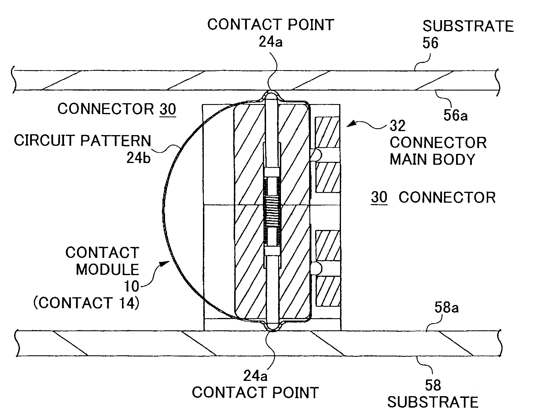
[0069]In FIG. 6, a connector 30 according to the present invention has the module 10 formed into a sheet structure as described above that is bent into a C-shape along the extending direction of the contacts 14 to be implemented to a connector main body 32.

[0070]The upper and lower contact points 24a of the contacts 14 of the contact module 10 protrude outward from both the upper and lower edges of the C-shaped contact 14 and form a convex shape. Thus, the contact points are prevented from receiving interference from surrounding portions. Also, since the slit 28 is formed between the convex-shaped contact points 24a, the contact points 24a are provided with spring characteristics and thereby sufficient contact force can be obtained.

[0071]The connector main body 32 has a pair of support members 34 and 36, a pair of cap members 38 and 40, a pair of push pins (slide members) 42 and 44, and a coil spring (elastic member) 46 (see FIGS. 6 and 9). The push pins 42 and 44, and the coil spri...

second embodiment

[0081]The connector 30 may be modified to have a configuration shown in FIG. 14. In this drawing, a connector 30a has a positioning member 47 instead of the coil spring 46. This positioning member 47, arranged between the pair of push pins 42 and 44, correctly positions the push pins 42 and 44 so as to push the contact points 24a by sliding the push pins. The coil spring 46 may also be used together with the positioning member 47. The above-described modifications can be applied to a connector 60 according to the present invention as well.

[0082]In the following, the connector according to the second embodiment of the present invention will be described with reference to FIG. 15.

[0083]The basic structure of a connector 60 according to the second embodiment of the present invention is identical to that of the connector 30 according to the first embodiment. The connector 60 is different from the connector 30 in that one of its contact points is extended so as to be connected to a cable...


PUM


Abstract

A new connector that is reduced in size and has a higher density of contacts implemented therein is provided. This connector has a contact module arranged on a connector main body. The contact module is formed into a sheet structure, and a plurality of contacts are arranged therein. Further, the contact module is bent into a C-shaped structure along the extending direction of the contacts, and is implemented to the connector main body in this state. Contact points of the connector are energized by sets of a coil spring and two push pins arranged on both sides of the coil spring so that these contact points protrude from holes formed at the connector main body.

Description

BACKGROUND OF THE INVENTION[0001]1. Field of the Invention[0002]The present invention relates to a connector.[0003]2. Description of the Related Art[0004]A connector is used to electrically connect a plurality of electronic devices or electronic parts.[0005]The connector can be classified into various types according to its configuration and the like.[0006]For example, based on mount mode, connectors can be divided into a substrate connector that is connected to a substrate, an LSI socket that is connected to an LSI, and a relay connector that is used for connecting a cable to another cable.[0007]Among the different types of connectors mentioned above, the substrate connectors can be further divided into a card edge type connector and a two-piece type connector.[0008]FIGS. 1 and 2 show examples of the card edge type connector used to connect a mother board 1 to a daughter card 2, wherein pads 3 arranged on patterns (not shown) formed at both sides of the daughter card 2 are held bet...

Claims


Application Information

Patent Timeline
Patent Type & Authority Patents(United States)
IPC IPC(8): H01R12/00G01R1/073H01R13/03H01R13/24H01R43/00
CPCH01R13/2421
Inventor SATO, SHIHOITO, TAKESHISHIMIZU, NOBORUMIYAZAWA, HIDEO
Owner FUJITSU COMPONENENT LTD
Why Eureka
Try Eureka