
Golf club head with customizable center of gravity

a golf club head and center of gravity technology, applied in the field of customizable golf club head and golf club, can solve the problems of increased energy transfer problem, increased deformation of golf balls, energy loss,

Inactive Publication Date: 2006-10-17
TOPGOLF CALLAWAY BRANDS CORP
View PDF9 Cites 62 Cited by
  • Summary
  • Abstract
  • Description
  • Claims
  • Application Information

AI Technical Summary

Benefits of technology

[0036]The present invention provides a means for fabricating heads having a center of gravity location that is determined late in the manufacturing process and that is selected to be appropriate for a specific player or player segment. The present invention preferably includes a face component and interchangeable aft-body components that are pre-manufactured and then selected for assembly based on the desired center of gravity location for that specific golf club head. The center of gravity location of the golf club head is preferably varied independently in the heel-toe and sole-crown directions to achieve desired levels of side spin and back spin for the specific player type. Golf club performance (trajectory and shot shape) is improved by adjusting the spin characteristics of the golf club head to better match the player type. A golf club having a tendency to provide a draw (right to left) shot shape can be provided to players who tend to hit a fade or slice (left to right). Also, a golf club having a tendency to provide a higher golf ball trajectory can be provided to players who tend to hit the golf ball lower than desired.
[0041]Another aspect of the present invention is assembly of the aft-body to the face component at a late stage of fabrication thereby allowing for any one of many aft-bodies, each having different center of gravity locations, to be bonded to the face component. Such late-stage assembly allows for mass customization of the center of gravity of a golf club head for high volume manufacturing.

Problems solved by technology

Most of the energy is transferred from the head to the golf ball, however, some energy is lost as a result of the collision.
However, this leads to greater deformations in the golf ball, and thus increases in the energy transfer problem.
Existing large volume driver heads (>300 cc) composed of conventional materials (titanium, steel) and conventional manufacturing methods (casting, forging, MIM, machining, etc.) are limited in the amount of discretionary material available for adjusting the center of gravity location of the golf club head.
This limits the ability to customize the performance characteristics of the head to best suit a particular player or segment of players.
Further, the center of gravity is not readily adjustable since the discretionary mass is in the form of parent metal or a discrete weight chip, both of which are established early in the head manufacturing process.
Therefore, customizing the center of gravity of conventional head designs is generally difficult and ineffective.

Method used


Image

  • Golf club head with customizable center of gravity
  • Golf club head with customizable center of gravity
  • Golf club head with customizable center of gravity

Examples


Embodiment Construction

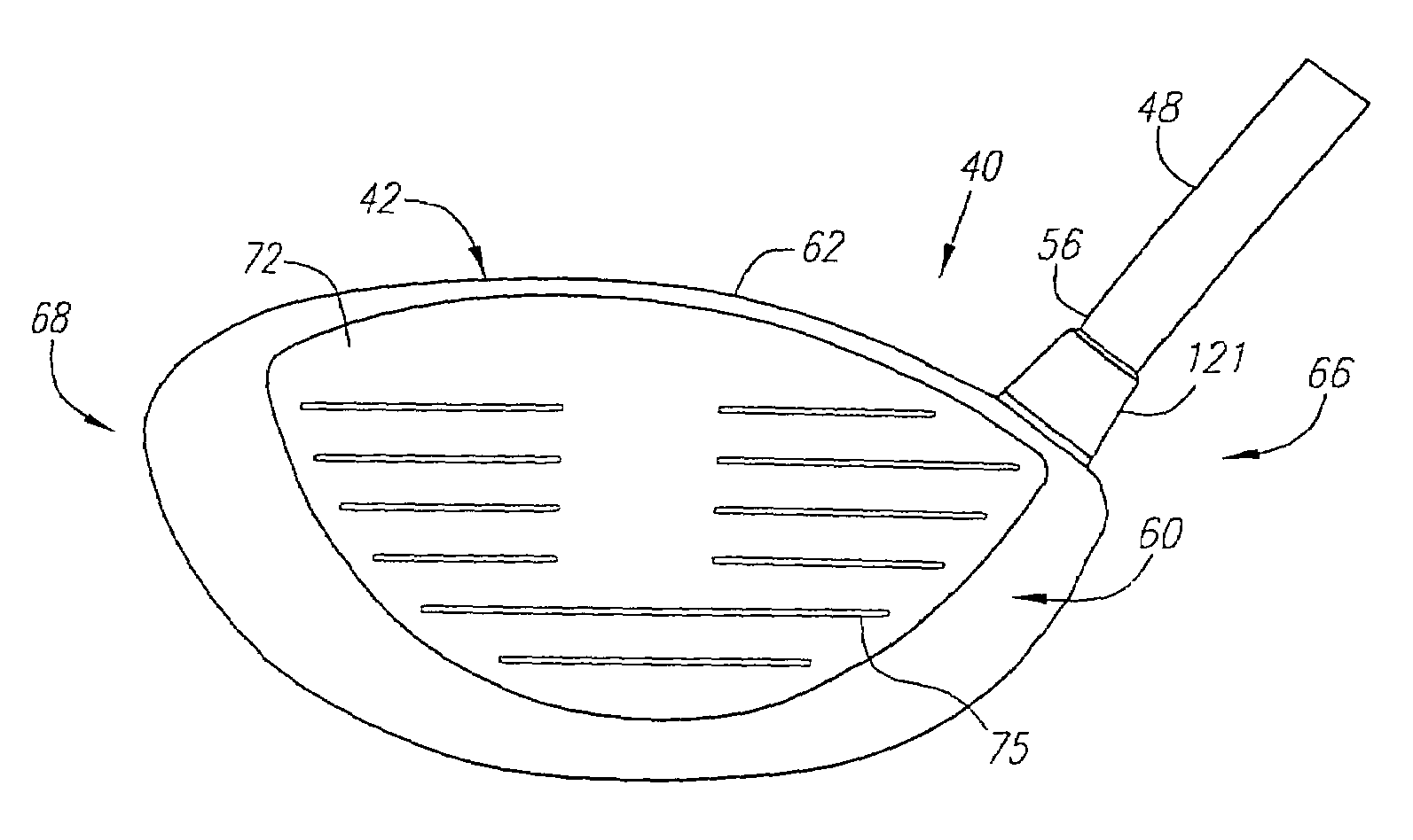
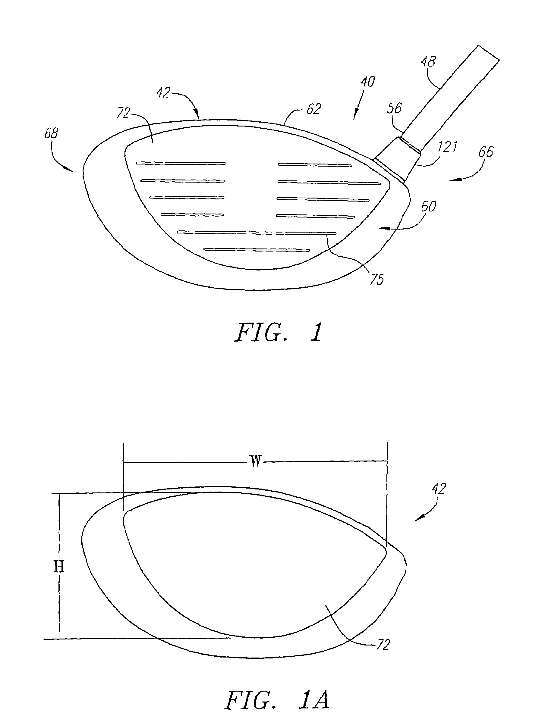
[0100]As shown in FIGS. 1–6A, a golf club is generally designated 40. The golf club 40 has a golf club head 42 with a hollow interior, not shown. Engaging the club head 42 is a shaft 48 that has a grip 50, not shown, at a butt end 52 and is inserted into a hosel 54 at a tip end 56.

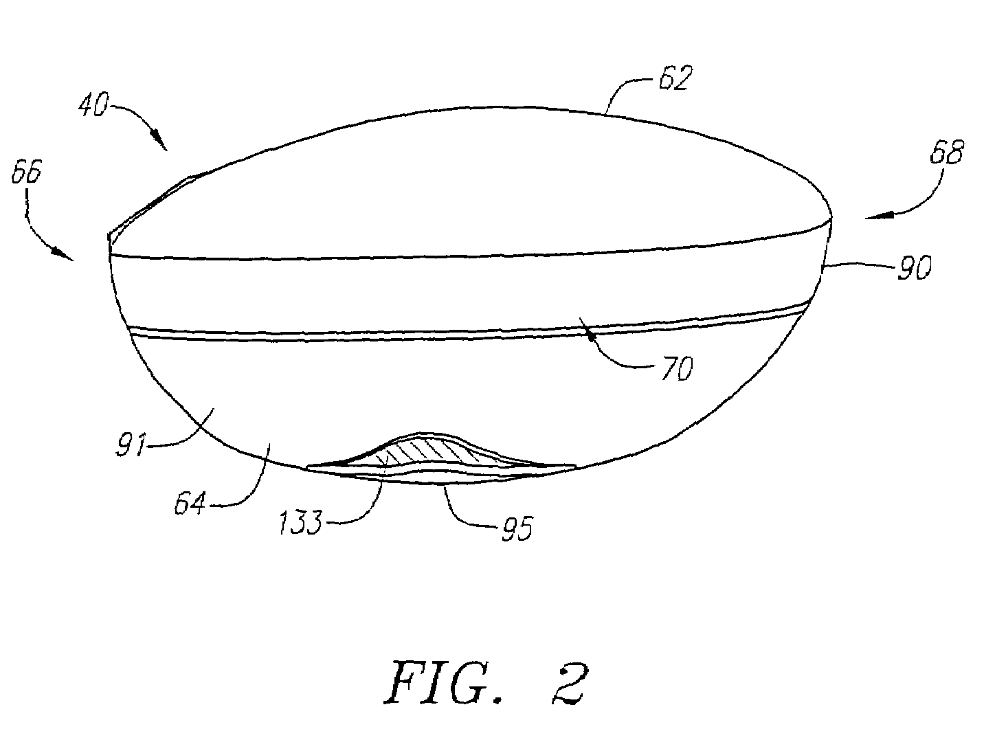
[0101]The club head 42 is generally composed of two components, a face component 60, and an aft-body 61. The aft-body 61 has a crown portion 62 and a sole portion 64. The club head 42 is preferably partitioned into a heel section 66 nearest the shaft 48, a toe section 68 opposite the heel section 66, and a rear section 70 opposite the face component 60. A sole weight member 133 is disposed within a sole undercut portion 133a of the sole portion. The sole weighing member has a mass ranging from 0.5 grams to 15 grams.

[0102]The face component 60 is generally composed of a single piece of metal, and is preferably composed of a forged metal material. More preferably, the forged metal material is a forged titani...


PUM


Abstract

A golf club (40) having a club head (42) with a face component (60) and an interchangeable aft-body (61) is disclosed herein. The face component (60) has a striking plate portion (72) and a return portion (74). The aft-body (61), which is attached to the return portion (74) of the face component (60), is selected from a plurality of aft-bodies, each having a different center of gravity location. Each of the aft-bodies (61) is composed of a crown portion (62), a sole portion (64), and a plurality of weights (122) for adjusting location of the center of gravity. An aft-body (61) is selected from the plurality of aft-bodies (61) based on its center of gravity location, so as to provide the club head (40) with a center of gravity location suited to a particular golfer.

Description

CROSS REFERENCES TO RELATED APPLICATIONS[0001]This application is a continuation-in-part application of U.S. patent application Ser. No. 10 / 925,529, filed on Aug. 24, 2004, which is a continuation-in-part application of U.S. patent application Ser. No. 10 / 709,213, filed on Apr. 21, 2004, now U.S. Pat. No. 6,926,619 which is a continuation application of U.S. patent application Ser. No. 10 / 249,510, filed on Apr. 15, 2003, now U.S. Pat. No. 6,739,983, which is a continuation-in-part application of U.S. patent application Ser. No. 09 / 683,860, filed on Feb. 22, 2002, now U.S. Pat. No. 6,582,323, which is a continuation-in-part application of U.S. patent application Ser. No. 09 / 906,889, filed on Jul. 16, 2001, now U.S. Pat. No. 6,491,592, which is a continuation-in-part of U.S. patent application Ser. No. 09 / 431,982, filed Nov. 1, 1999, now U.S. Pat. No. 6,354,962.STATEMENT REGARDING FEDERALLY SPONSORED RESEARCH OR DEVELOPMENT[0002]Not ApplicableBACKGROUND OF THE INVENTION[0003]1. Field ...

Claims


Application Information

Patent Timeline
Patent Type & Authority Patents(United States)
IPC IPC(8): A63B53/06A63B53/04A63B53/02
CPCA63B53/02A63B53/0466A63B2053/0408A63B2053/0412A63B2053/0416A63B2053/0462A63B2053/0491A63B2209/00A63B2053/0433A63B2053/0437A63B2053/0458A63B53/0412A63B53/0462A63B53/0437A63B53/0458A63B53/0408A63B53/0416A63B53/0433A63B60/02A63B53/04
Inventor STEVENS, DANIEL M.SMITH, GARTH W.HELMSTETTER, RICHARD C.CACKETT, MATTHEW T.ROLLNSON, AUGUSTIN W.GALLOWAY, J. ANDREWHOCKNELL, ALAN
Owner TOPGOLF CALLAWAY BRANDS CORP
Learn More