Method and apparatus enhanced acoustic mud pulse telemetry

a technology of acoustic mud pulse telemetry and signal enhancement, which is applied in the field of telemetry, can solve the problems of impeded acoustic conditions, telemetry signal can often be degraded to a point where conventional mud pulse telemetry is either impossible or impractical, and achieves enhanced acoustic mud pulse telemetry and improved acoustic conditions at the top of the surface system

Inactive Publication Date: 2006-10-17
SCHLUMBERGER TECH CORP
View PDF14 Cites 11 Cited by
  • Summary
  • Abstract
  • Description
  • Claims
  • Application Information

AI Technical Summary

Benefits of technology

[0008]Thus, it is an object of the present invention to provide a system and method for enhanced acoustic mud pulse telemetry wherein the acoustic conditions at the top of the surface system is improved.
[0016]According to another embodiment of the invention, a combination of the reflector and a multiplicity of pressure sensors are used, in combination with a processor that combines the signals from the pressure sensors so as to improve the signal to noise ratio. At least one of the pressure sensors is preferably placed upstream of the reflector.

Problems solved by technology

It is known that the reception of acoustic telemetry signals travelling through the drilling fluid, often referred to as mud pulse telemetry becomes more difficult with increasing well depth, and with very viscous drilling fluids.
Although some of the difficulty in signal reception is an inevitable consequence of the attenuation of the acoustic signal in its passage up the mud column, it is also impeded by the acoustic conditions at the top of the mud column inside the surface system.
The impeded acoustic conditions can take various forms, among these being reflections generated by equipment such as pulsation dampeners that reduce the received signal and noise from the mud pumps and other equipment that interferes with the signal.
Because of signal attenuation and impeded acoustic conditions in the surface system, the telemetry signal can often be degraded to a point where conventional mud pulse telemetry is either impossible or impractical.
However, a disadvantage of this type of method is that it requires a measurement of the mud pump piston position and fails if the pump noise changes after calibration.
A disadvantage of this type of system is that it does not adapt to changing acoustic conditions, and therefore the performance will ordinarily degrade over time.
However, a disadvantage of this type of arrangement is that all the receivers have similar signal to noise ratio.

Method used


Image

  • Method and apparatus enhanced acoustic mud pulse telemetry
  • Method and apparatus enhanced acoustic mud pulse telemetry
  • Method and apparatus enhanced acoustic mud pulse telemetry

Examples


Embodiment Construction

[0025]The following embodiments of the present invention will be described in the context of certain drilling arrangements, although those skilled in the art will recognize that the disclosed methods and structures are readily adaptable for broader application. Where the same reference numeral is repeated with respect to different figures, it refers to the corresponding structure in each such figure.

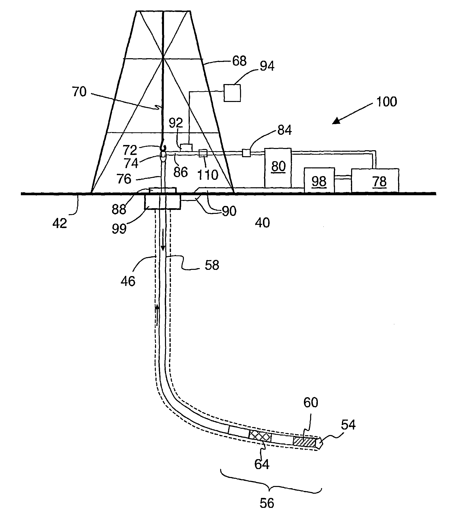
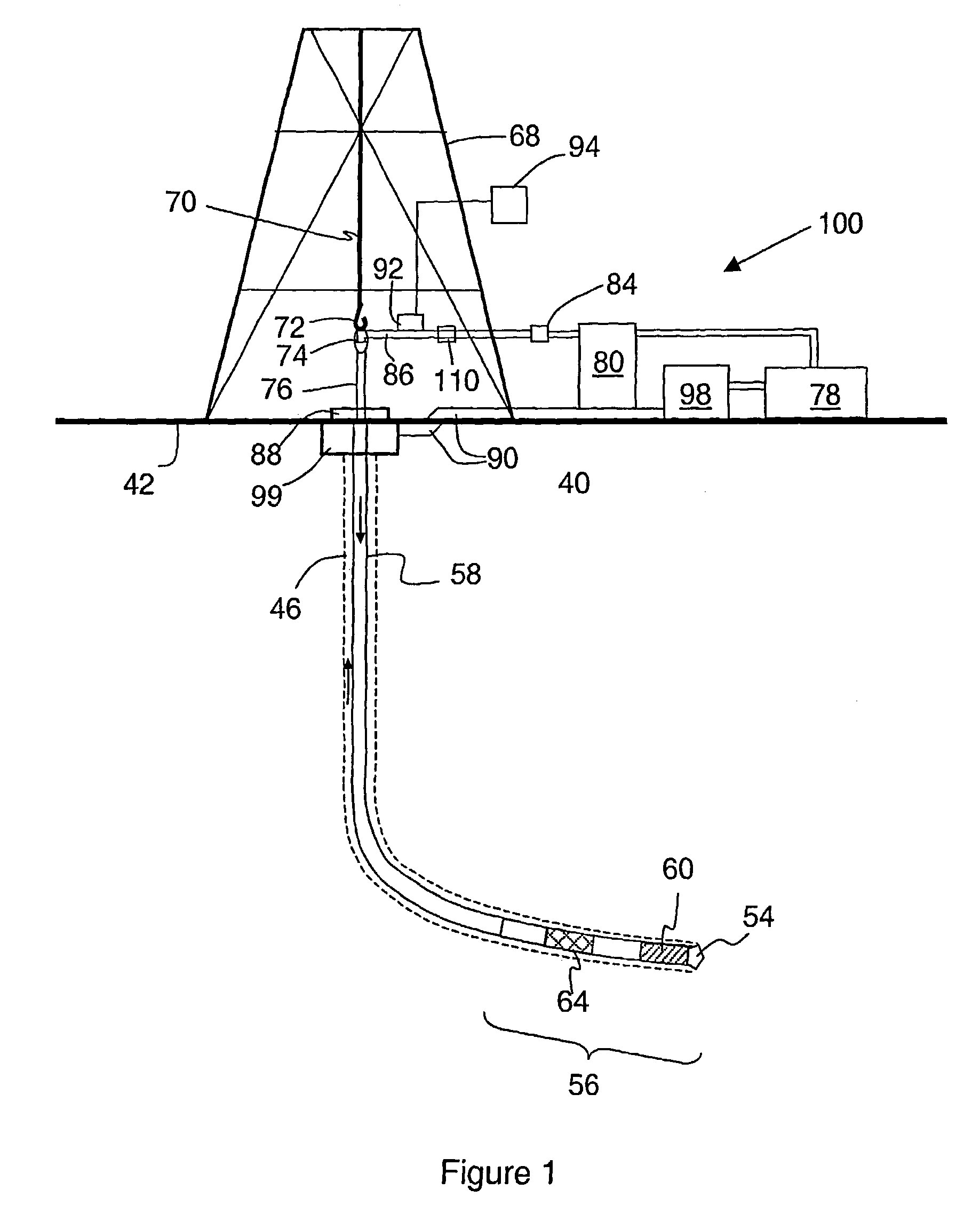
[0026]FIG. 1 shows a system for enhanced acoustic mud pulse telemetry during drilling, according to a preferred embodiment of the invention. Drill string 58 is shown within borehole 46. Borehole 46 is located in the earth 40 having a surface 42. Borehole 46 is being cut by the action of drill bit 54. Drill bit 54 is disposed at the far end of the bottom hole assembly 56 that is attached to and forms the lower portion of drill string 46. Bottom hole assembly 56 contains a number of devices including various subassemblies 60. According to the invention measurement-while-drilling (MWD) suba...


PUM


Abstract

A method and system for telemetry through a drilling fluid during drilling is disclosed. A reflector (110) is positioned downstream from the drilling mud pumps (80) and causes reflected pressure waves having the same pressure polarity as incident pressure waves traveling upwards. At least one pressure sensor (92) is positioned below the reflector (110) to sense pressure in the drilling fluid. The reflector can be a fixed orifice plate or an adjustable aperture.

Description

FIELD OF THE INVENTION[0001]The present invention relates to the field of telemetry during borehole drilling. In particular, the invention relates to a method and apparatus for signal enhancement for acoustic mud pulse telemetry.BACKGROUND OF THE INVENTION[0002]It is known that the reception of acoustic telemetry signals travelling through the drilling fluid, often referred to as mud pulse telemetry becomes more difficult with increasing well depth, and with very viscous drilling fluids. Although some of the difficulty in signal reception is an inevitable consequence of the attenuation of the acoustic signal in its passage up the mud column, it is also impeded by the acoustic conditions at the top of the mud column inside the surface system.[0003]The impeded acoustic conditions can take various forms, among these being reflections generated by equipment such as pulsation dampeners that reduce the received signal and noise from the mud pumps and other equipment that interferes with t...

Claims


Application Information

Patent Timeline
Patent Type & Authority Patents(United States)
IPC IPC(8): G01V8/14E21B21/00E21B47/18
CPCE21B47/18E21B2021/006E21B21/085
Inventor JEFFRYES, BENJAMIN PETERMORIARTY, KEITH ALANREYES, SANDRA DENISSE
Owner SCHLUMBERGER TECH CORP
Why Eureka
Try Eureka