Apparatus and method for allowing user to track path of travel over extended period of time

a technology of extended period and applicability, applied in the direction of sustainable buildings, navigation instruments, instruments, etc., can solve the problems of wasting power, unable to quickly achieve the satellite lock, and limiting the maximum number of waypoints that can be designated

Active Publication Date: 2006-10-17
BUSHNELL
View PDF16 Cites 123 Cited by
  • Summary
  • Abstract
  • Description
  • Claims
  • Application Information

AI Technical Summary

Benefits of technology

[0011]The present invention overcomes the above-described and other problems and disadvantages in the prior art by providing an apparatus and method for allowing a moving user to automatically periodically determine and store his or her own current geographic locations over an extended period of time, to display the series of such locations as an indication of the user's path of travel, and to actively assist the user in returning to an earlier location, either by traveling back along the path earlier traveled or by traveling along a more direct route.
[0013]The housing substantially encloses and protectively houses the sensitive components of the apparatus, protecting them from water, moisture, dust, and other environmental hazards. The GPS receiver functions, in a substantially conventional manner, to lock onto and receive signals from a plurality of orbiting satellites and, based thereon, to determine the current geographic location of the apparatus and the user with respect to the satellites. The antenna is connected to the GPS receiver and facilitates reception of the satellite signals used by the GPS receiver to determine location. The fastening mechanism is connected to the antenna and allows for removably coupling the antenna with an item worn or carried by the user. This feature allows for positioning the antenna for best reception of the satellite signals and, if the lock indicator is incorporated into the fastening mechanism, for locating the lock indicator for best visibility or audibility by the user. The satellite lock indicator functions, when the apparatus is in tracking mode, to communicate to the user that either the satellite lock necessary for the GPS receiver to determine the user's current location has not been achieved or that the ability of the battery to provide power is critically low. It will be appreciated that this feature is especially important and advantageous as the user might, without such a warning, travel for a substantial time or distance with no corresponding locations stored in the memory.
[0014]The processor controls, in a substantially conventional manner, internal electronic operation of the apparatus and coordinates functioning of the various other components, as appropriate, in both normal and tracking modes. The battery provides power to the various other components of the apparatus that require power in order to operate. It will be appreciated that the ability or capacity of the battery to provide such power is limited, and therefore it is an important feature of the present invention to make the most efficient use of this ability or capacity in order to extend and maximize the usefulness of the apparatus, particularly its ability to continue tracking the user's movement over time.
[0015]The timer measures, in tracking mode, a preestablished time interval during which the apparatus is in a “sleep” or minimum power consumption mode. At the end of the interval, the GPS receiver automatically determines the user's current location, which is then stored in the memory. Once the current location is determined and stored, the apparatus automatically re-enters the sleep mode and the timer-measured interval begins again. This process automatically repeats so long as the apparatus is in tracking mode. The memory receives, stores, and provides for recalling the series of locations determined by the GPS receiver. It will be appreciated that this series of locations, when displayed simultaneously, corresponds to or reflects the user's path of travel over time. The display displays the current location, as determined by the GPS receiver; the series of locations stored in the memory; and any other desired information. When the apparatus is in tracking mode, the display is automatically turned off in order to conserve power and thereby extend or maximize the usefulness of the apparatus. The input mechanism allows the user to provide input to the processor and other components.
[0017]Thus, it will be appreciated that the apparatus of the present invention provides a number of substantial advantages over the prior art, including, for example, increased usefulness and safety resulting from being able to track automatically for at least 24 hours and preferably between 36 hours and 48 hours, which is substantially longer than is possible with similar prior art hand-held, battery-powered devices. Thus, the power conservation features of the present invention advantageously enable it to continue tracking long after prior art devices have depleted their power and ceased to operate.
[0019]Additionally, the return tracking mode or feature advantageously frees the user from having to refer continuously to the display by actively warning the user whenever his or her course deviates by a pre-established amount from the return path or route, thereby allowing the user to quickly adjust his or her course so as to more reliably and efficiently return to the earlier location.

Problems solved by technology

Prior art devices exist for determining and storing locations but, unfortunately, suffer from a number of drawbacks and disadvantages.
Unfortunately, the designation of waypoints requires active participation by the user.
Furthermore, the maximum number of waypoints that can be designated is likely to be extremely limited because the waypoint concept generally refers to a very limited number of special locations designated for very particular purposes, not an unlimited number of non-special locations designated merely for general record-keeping purposes.
When the user does remember to make a designation, he or she may remove the electronic device from its protective or carrying environment only to find it impossible to quickly achieve the satellite lock necessary to determine the current location, and so the user must travel still further until the required lock can be established.
Also, in order to designate waypoints, the device must either be left on continuously, thereby draining power and severely limiting both the amount of time in which new waypoints may be designated and the amount of time in which stored waypoints may be recalled, or the device must be turned on and off each time a designation is made.
Turning the device on and off in this manner can itself result in a substantial power drain, and so the frequency with which waypoints are designated must be reduced.
Thus, these particular prior art devices do not provide a practical and reliable mechanism for creating a record of the user's previous locations in such a manner as to allow for better understanding his or her path of travel.
Unfortunately, these prior art devices quickly deplete their battery power, and once the power fails, no further locations are determined and the user can no longer display the record of previous locations.
If the user travels for longer than a few hours with no ability to charge the battery, he or she will not be able to display the path of travel if the need arises to backtrack, creating a potentially dangerous situation.
Unfortunately, because the location-determining mechanisms are carried on vehicles, there are none of the weight, size, or power consumption restrictions that a hand-held device would require.
It will therefore be appreciated that these prior art systems are neither useful nor feasibly adaptable for solving the present problem of allowing hikers and other traveling individuals to save and recall their previous locations so as to better understand their path of travel.

Method used


Image

  • Apparatus and method for allowing user to track path of travel over extended period of time
  • Apparatus and method for allowing user to track path of travel over extended period of time
  • Apparatus and method for allowing user to track path of travel over extended period of time

Examples


Embodiment Construction

, below.

BRIEF DESCRIPTION OF THE DRAWINGS

[0021]A preferred embodiment of the present invention is described in detail below with reference to the attached drawing figures, wherein:

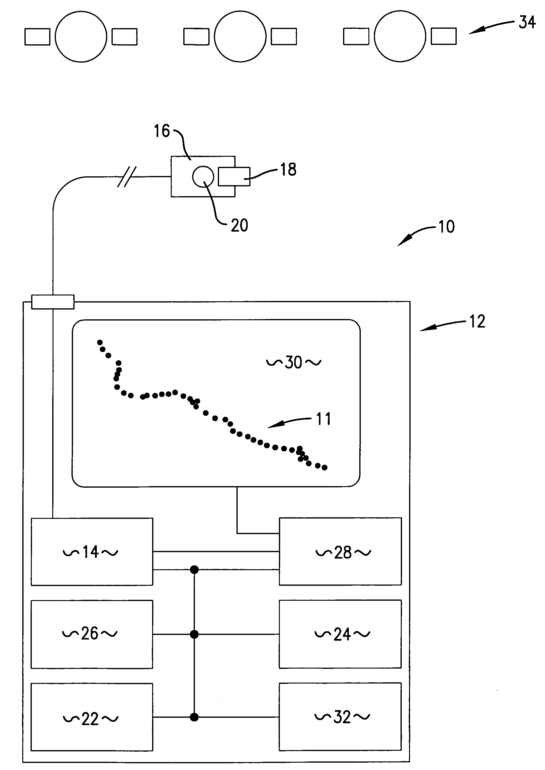
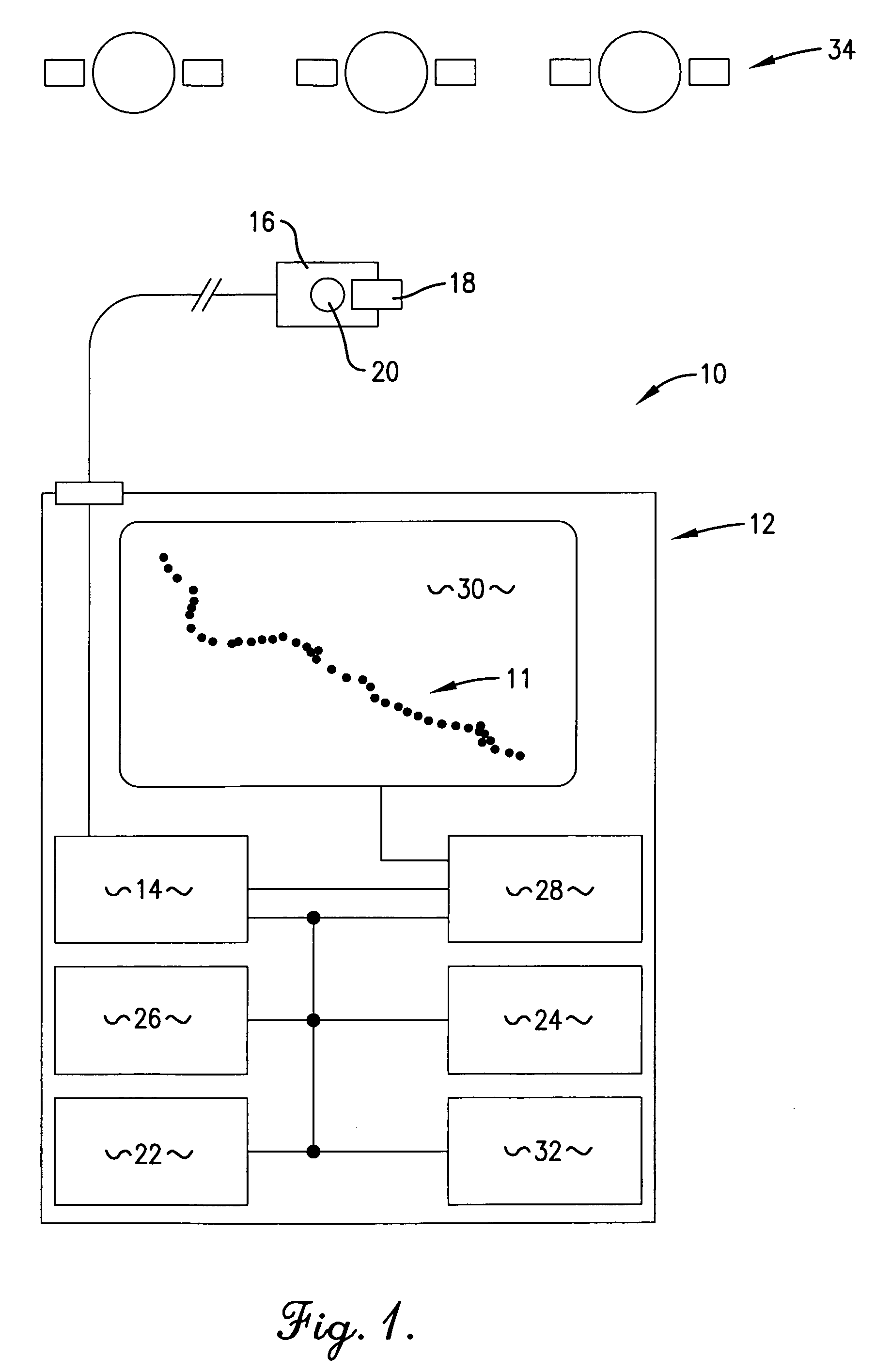
[0022]FIG. 1 is a block diagram of a preferred embodiment of the apparatus of the present invention;

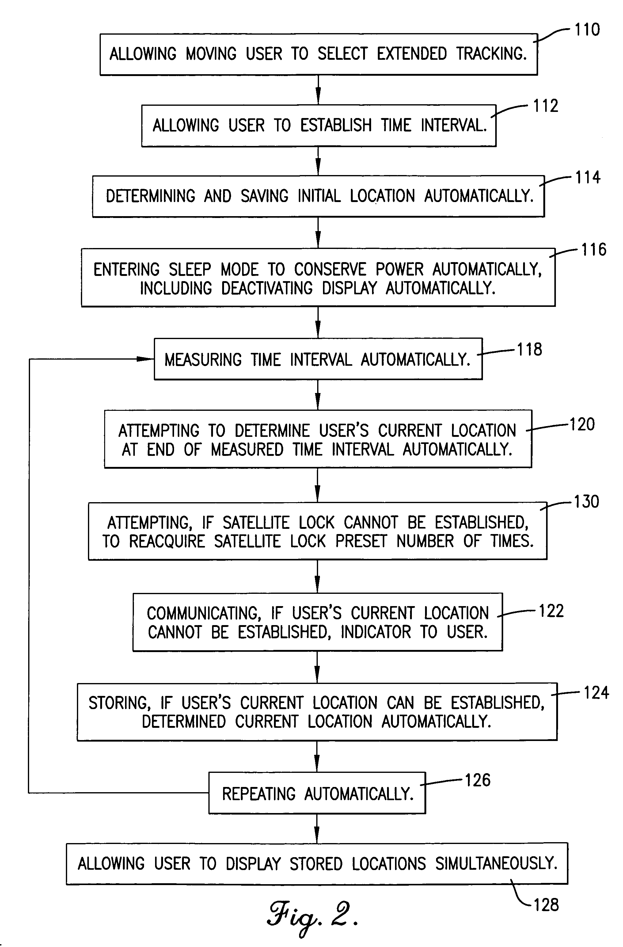
[0023]FIG. 2 is a flowchart of steps involved in a preferred embodiment of a forward tracking mode or feature of the method of the present invention, as may be implemented by the apparatus of FIG. 1; and

[0024]FIG. 3 is a flowchart of steps involved in a preferred embodiment of a return tracking mode or feature of the method of the present invention, as may be implemented by the apparatus of FIG. 1.

DETAILED DESCRIPTION OF A PREFERRED EMBODIMENT

[0025]With reference to the figures, an apparatus 10 and method for allowing a moving user to automatically track his or her own movement over time is herein described, shown, and otherwise disclosed in accordance with a preferred embodiment of the present invention. Mo...


PUM


Abstract

An apparatus (10) and method for allowing a moving user to automatically determine and store locations (11) over an extended period of time, to display the series of such locations (11), and to actively assist in returning to an earlier location. The apparatus (10) includes an antenna (16) for facilitating satellite lock, a fastening mechanism (18) for positioning the antenna (10) for best reception, and a satellite lock indicator (20) for communicating loss of satellite lock. The apparatus (10) also includes a timer (26) for measuring an interval during which the apparatus (10) is in a power-conserving sleep mode, and after which the user's current location is automatically determined. Active assistance in returning to an earlier location, either by traveling back along the path earlier traveled or by traveling along a more direct route, is accomplished by warning the user whenever the user's course deviates from the path or route.

Description

RELATED APPLICATIONS[0001]The present U.S. non-provisional patent application is a continuation-in-part of earlier-filed U.S. non-provisional patent application titled “Apparatus and Method for Allowing User to Track Path of Travel Over Extended Period of Time”; Ser. No. 10 / 845,394, filed May 13, 2004. As such, the present application claims, with regard to all common subject matter, priority benefit of the identified earlier-filed application, and hereby incorporates by reference the earlier-filed application in its entirety.BACKGROUND OF THE INVENTION[0002]1. Field of the Invention[0003]The present invention relates broadly to apparatuses and methods for allowing a moving user to track his or her own movement over time and for actively assisting the user in returning to an earlier location. More particularly, the present invention concerns an apparatus and method for allowing the moving user to automatically periodically determine and store his or her own current geographic locati...

Claims


Application Information

Patent Timeline
Patent Type & Authority Patents(United States)
IPC IPC(8): G01S5/14G01S19/48G01C21/20G01S1/00G01S19/51
CPCG01C21/20G01S19/34G06F17/30241G01S19/51Y02B60/188G06F16/29Y02D10/00
Inventor LALIK, CHRISTOPHERCROSS, BILLBALL, RICHARD
Owner BUSHNELL
Why Eureka
Try Eureka