
Routing apparatus

Inactive Publication Date: 2006-10-17
FUJITSU LTD
View PDF9 Cites 32 Cited by
  • Summary
  • Abstract
  • Description
  • Claims
  • Application Information

AI Technical Summary

Benefits of technology

[0030]Accordingly, an object of the present invention is to provide a low-cost and compact routing apparatus.
[0031]Another object of the present invention is to reduce the number of CAMs used to thereby lower cost and raise the mounting efficiency of the routing apparatus.
[0032]A further object of the present invention is to improve the reliability of a routing apparatus by making it possible to resume operation following the occurrence of a failure.

Problems solved by technology

The processing speeds of routers and ATM switches is increasing with the explosive spread of the Internet and ATM networks.
However, an increase in the capacity CAMs is accompanied by the need for a large number of CAMs if the CAMs are of the usual capacity.
It is difficult to package all the CAMs on an ordinary LSI chip.
As a consequence, system start-up takes considerable time and so does recovery at the time of failure.
Since the conventional CAM does not possess a statistical processing function, the CAM cannot execute statistical processing at the time of multiple hits, namely when there are multiple items of entry key data for search key data.
Consequently, it is required that the MPU of the main controller calculate statistical information by program processing using the main memory (MM), which results in a large head of the MPU.
The reason for this is that in an arrangement in which a line card accommodates lines having different speeds, costs rise because all of the line cards will require a costly CAM of maximal speed.
Depending upon the network, there will be line cards that cannot be used and situations will arise in which the lines accommodated by line cards are too few in number.
In other words, the conventional routing apparatus is such that the line cards have a poor line accommodating efficiency, and the apparatus is high is cost.

Method used


Image

  • Routing apparatus
  • Routing apparatus
  • Routing apparatus

Examples


Embodiment Construction

[0066](A) System Configuration

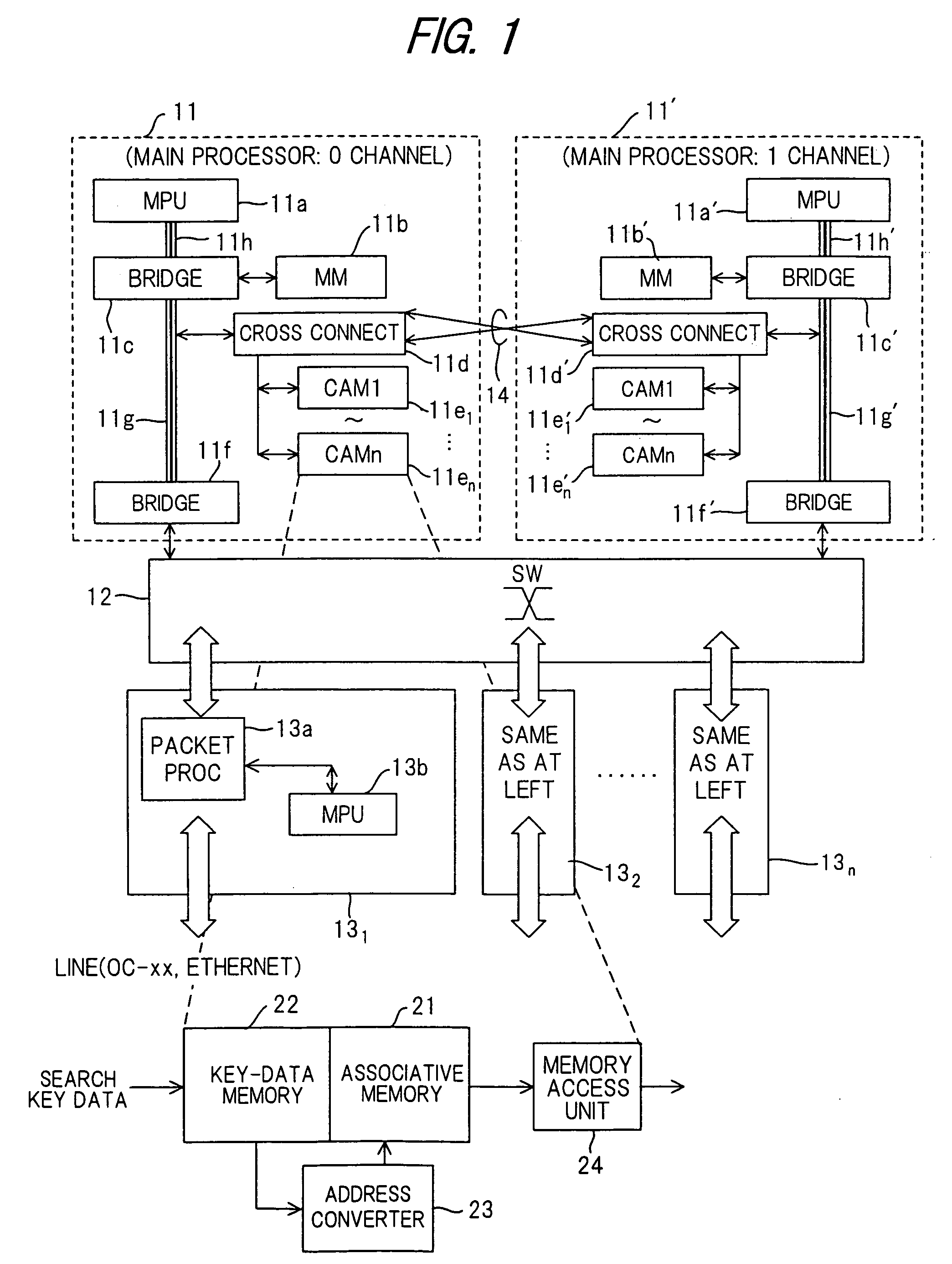
[0067]FIG. 1 is a block diagram showing the configuration of a system according to the present invention. The system includes identically constructed main controllers (main controllers of 0 and 1 channels) 11, 11′ that are redundant in order to improve reliability; a switch 12; and line cards (line interfaces) 131˜13n that accommodate various lines such as SONET / SDH and Ethernet lines, etc.

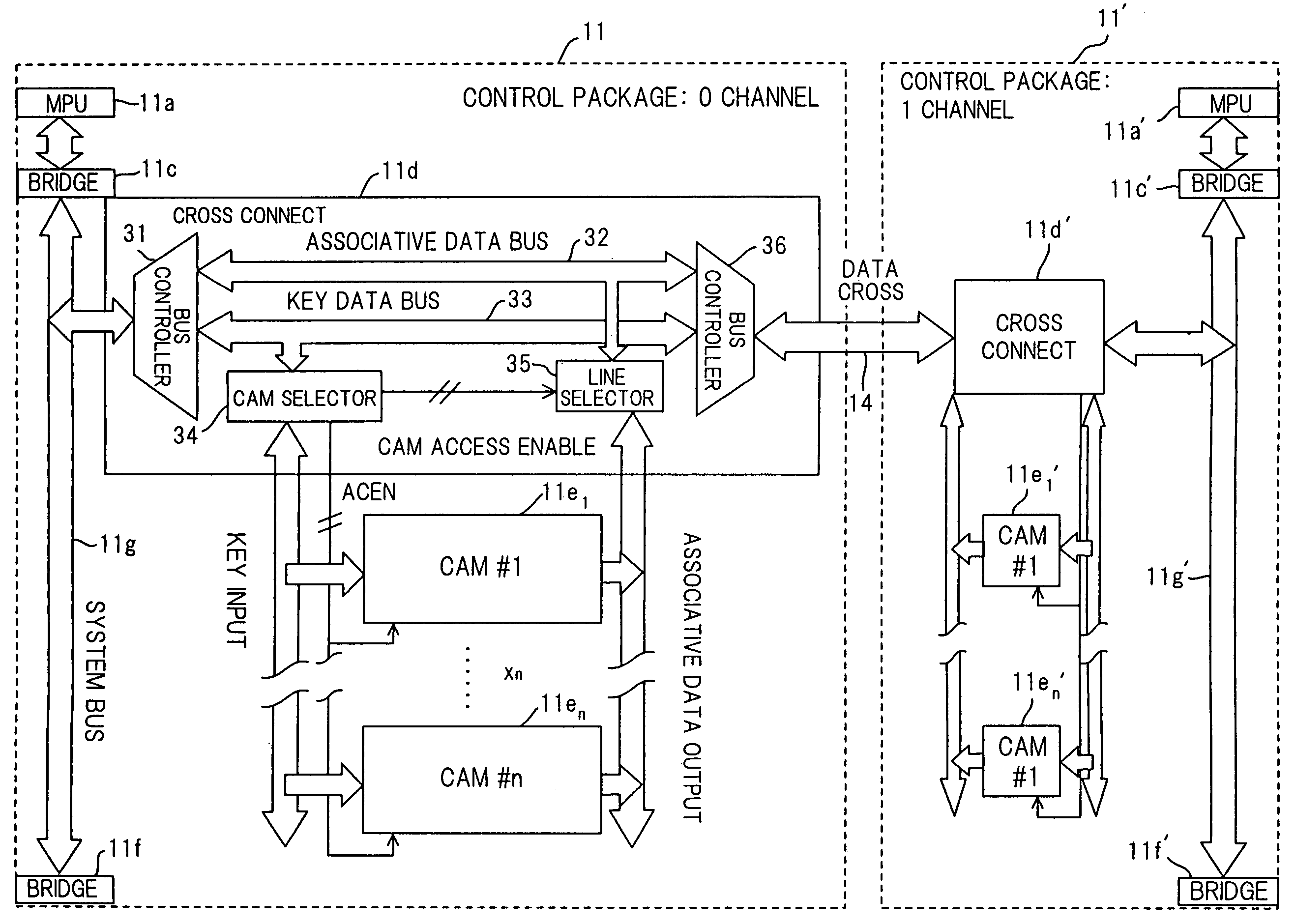
[0068]The main controllers 11, 11′ respectively include: (1) main processors (MPU) 11a, 11a′; (2) main memories (MM) 11b, 11b′; (3) MPU bus conversion bridges 11c, 11c′ for connecting various devices such as input / output units and CAMs, which are connected to a system bus, to the MPU; (4) cross-connect units 11d, 11d′ for communicating with the CAMs of the other channel; (5) pluralities of CAMs 11e1˜11en, 11e1′˜11en′ provided for corresponding ones of line speeds and selectable depending upon line speed; and (6) bus conversion bridges 11f, 11f′ for accepting data addr...


PUM


Abstract

Disclosed is a routing apparatus for obtaining routing data conforming to a destination address of a packet that arrives from a line, adding the routing data onto the packet, and switching the packet based upon the routing data to send the packet to a prescribed line. The routing apparatus has a main controller equipped with content addressable memories (CAMs) corresponding to respective ones of line speed. When search key data with an attached line identifier is received from a line card, routing data is generated by the content addressable memory (CAM) corresponding to the line speed and the routing data is sent to the line card. The line card adds routing data of which it has been notified by the main controller onto a packet and then outputs the packet. A switch to which a packet having attached routing data is input from a prescribed line card switches the packet based upon the routing data and sends the packet to another line card.

Description

BACKGROUND OF THE INVENTION[0001]This invention relates to a routing apparatus that uses a CAM (Content Addressable Memory) when routing is performed in a network such as the Internet or ATM network. More particularly, the invention relates to a routing apparatus for obtaining routing data, which conforms to the destination address of a packet that arrives from a line, from a CAM, adding the routing data onto the packet, and switching the packet based upon this routing data to send the packet to a prescribed line.[0002]The processing speeds of routers and ATM switches is increasing with the explosive spread of the Internet and ATM networks. Owing to lines packed in higher densities, tables for searching data (routing data) necessary for routing and switching are increasing in capacity.[0003]Methods of searching routing data rely upon conventional processing technology using a CAM. However, an increase in the capacity CAMs is accompanied by the need for a large number of CAMs if the ...

Claims


Application Information

Patent Timeline
IPC IPC(8): G06F15/173H04L29/08H04L12/701H04L12/773
CPCH04L45/00H04L45/54H04L45/60H04L45/7453H04L49/3009H04L2012/562
Inventor SATO, KAZUYUKITERASAWA, TAKUYA
Owner FUJITSU LTD
Learn More