Magnetic random access memory

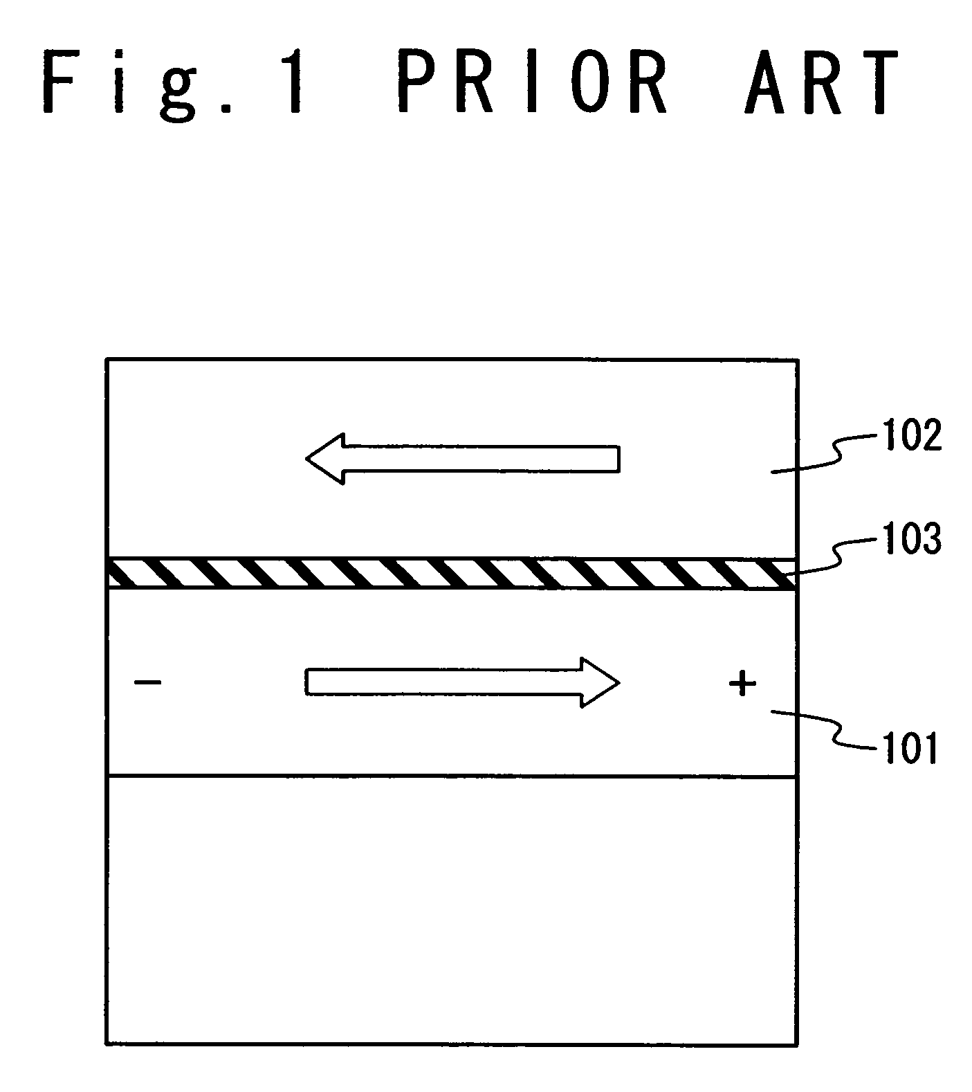
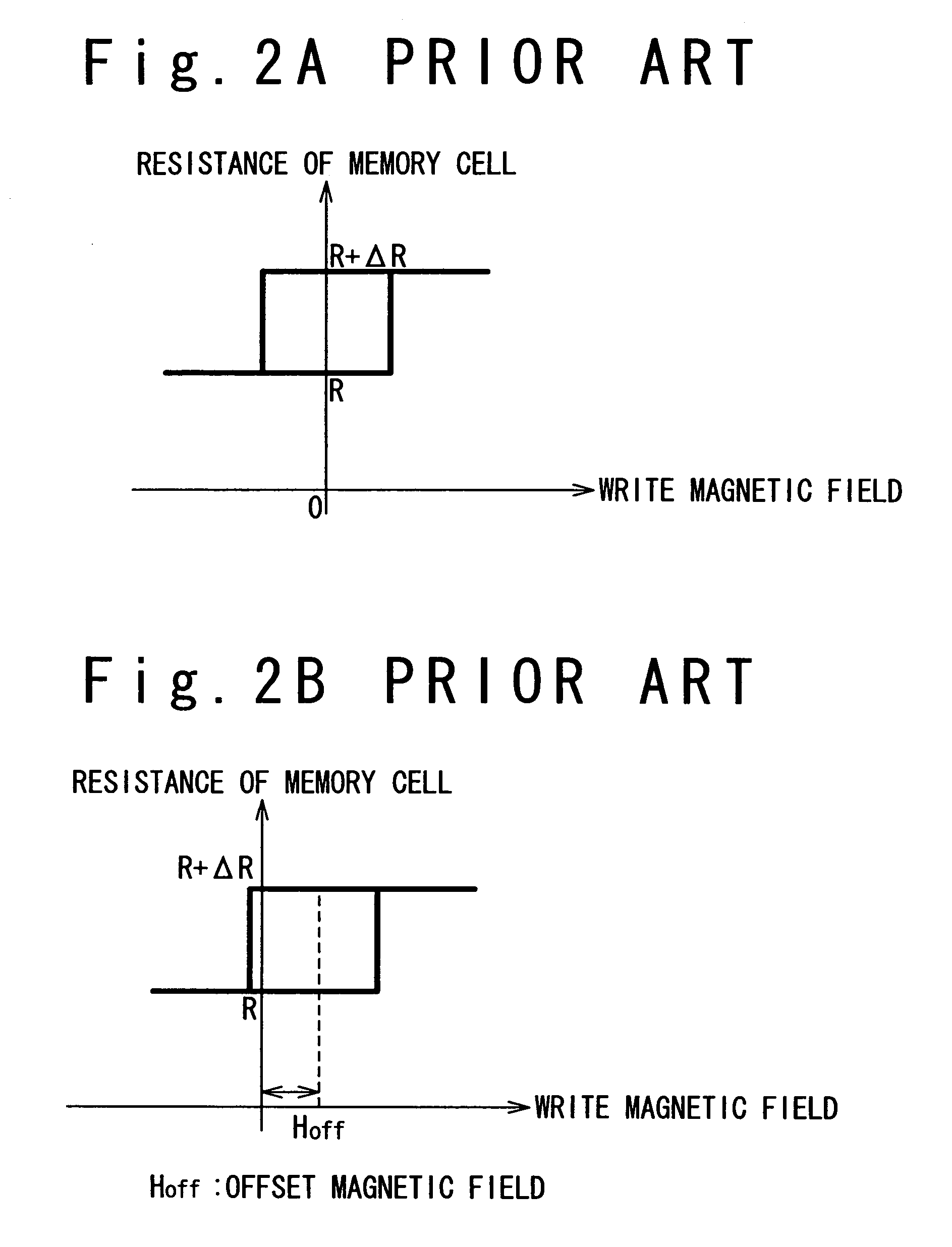
a random access and memory technology, applied in the field of magnetic random access memory, can solve the problems of difficult to cancel the orange peel coupling effect by the magneto-static coupling effect in each of large number of memory cells, the uniform magnetic field received by the free layer 102, and the cancellation of the orange peel coupling effect, etc., to achieve uniform reduction of offset magnetic fields, suppress offset magnetic fields, and reduce the offset magnetic field of memory cells

Inactive Publication Date: 2006-10-24
NEC CORP
View PDF8 Cites 35 Cited by
  • Summary
  • Abstract
  • Description
  • Claims
  • Application Information

AI Technical Summary

Benefits of technology

[0020]An object of the present invention is to provide a technique for more effectively reducing an offset magnetic field in a memory cell of an MRAM.
[0021]Another object of the present invention is to provide a technique for uniformly reducing an offset magnetic field over the whole of inside of the memory cell of an MRAM.
[0022]Another object of the present invention is to provide a technique for suppressing an adverse influence to elimination of an offset magnetic field in a memory cell of an MRAM through a manufacturing deviation.

Problems solved by technology

As described above, the magnetic field received by the free layer 102 is not uniform, and it is difficult that the orange peel coupling effect is canceled by the magneto-static coupling effect over the entire inner portion of the memory cell.
Furthermore, recent progress in very fine technique for the MRAM may makes it difficult to cancel the orange peel coupling effect by the magneto-static coupling effect in each of large numbers of memory cells contained in the MRAM.
The increase of these deviations may makes it difficult to cancel the orange peel coupling effect and the magneto-static coupling effect in each of the memory cells, and disturbs that the offset magnetic field is eliminated in each of these memory cells contained in the memory cell arrays of the MRAM.
However, these conventional examples do not describe that an offset magnetic field of the free layer of the magneto-resistance element is eliminated.

Method used


Image

  • Magnetic random access memory
  • Magnetic random access memory
  • Magnetic random access memory

Examples


first embodiment

[First Embodiment]

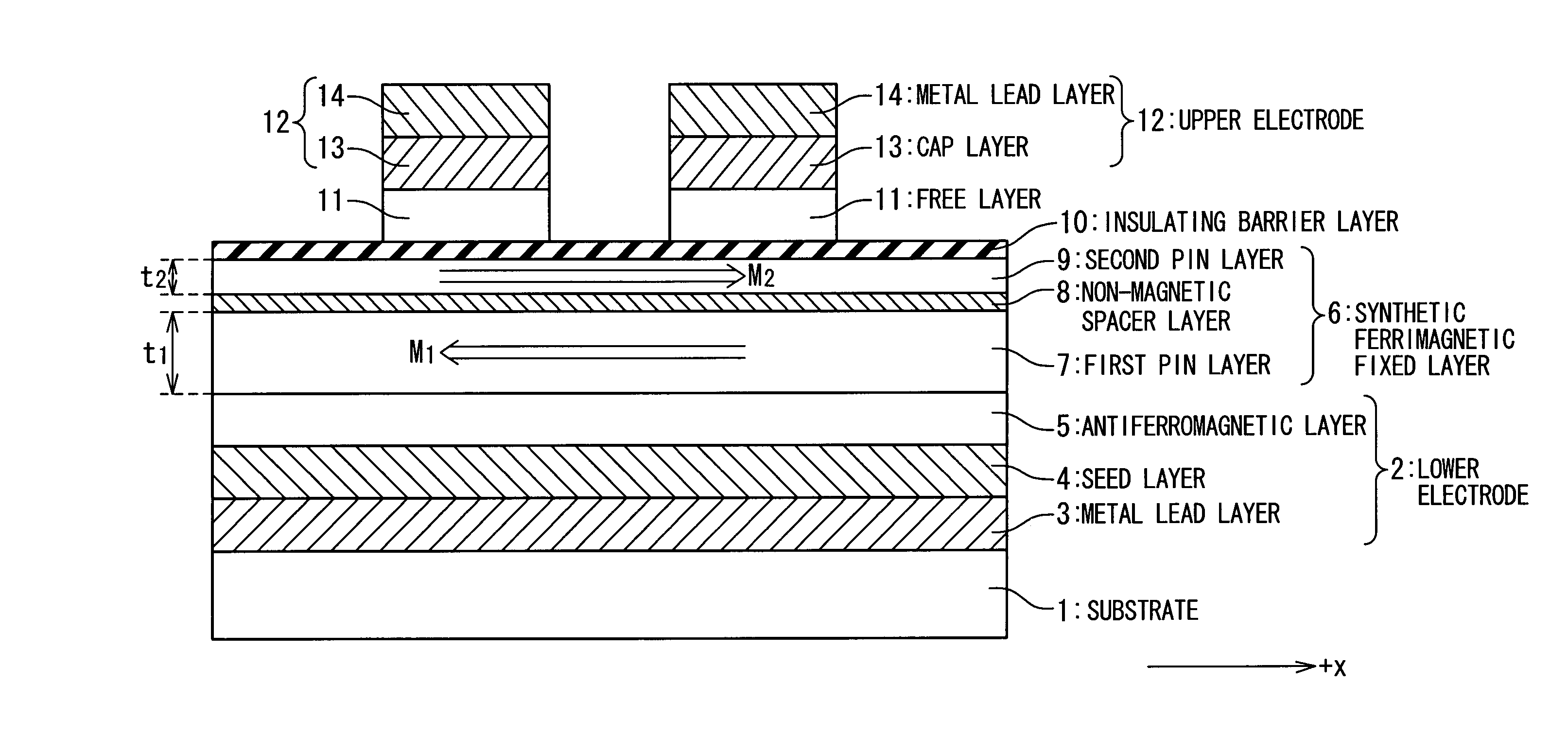
[0057]FIG. 7 indicates a structure of the MRAM according to a first embodiment of the present invention. It should be noted that for a better understanding of this structure, a ratio of the vertical length to the horizontal length in the structure of the MRAM shown in FIG. 7 is different from in a ratio in the structure of the actual MRAM.

[0058]The MRAM in the first embodiment is composed of a substrate 1 and a lower electrode 2. The substrate 1 has been formed on the substrate 1. The lower electrode 2 contains a metal lead layer 3, a seed layer 4, and an anti-ferromagnetic layer 5. The metal lead layer 3 is typically formed of Al or Cu. The seed layer 4 is typically formed from a Ta film or a synthetic film of a Ta film and a Ru film. The anti-ferromagnetic layer 5 is formed of anti-ferromagnetic material, and is typically formed of FeMn, IrMn, or PtMn.

[0059]A synthetic ferrimagnetic fixed layer 6 is formed on the lower electrode 2. The synthetic ferrimagnetic fix...

second embodiment

[Second Embodiment]

[0092]FIG. 11 shows the structure of an MRAM according to the second embodiment of the present invention. It should be noted that a ratio of the horizontal length and the vertical length in the structure of the MRAM shown in FIG. 11 is different from a ratio of them in the structure of the actual MRAM, for a better understanding of this structure.

[0093]In the MRAM of the second embodiment, both the orange peel coupling effect and the magneto-static coupling effect are suppressed by a synthetic ferrimagnetic fixed layer 6′ having a structure which is different from that of the synthetic ferrimagnetic fixed layer 6 in the first embodiment.

[0094]The synthetic ferrimagnetic fixed layer 6′ in the MRAM of the second embodiment contains a first pinned layer 7′, a plurality of non-magnetic spacer layers 8′, and second pinned layers 9′ formed on the non-magnetic spacer layers 8′. Both the first pinned layer 7′ and the second pinned layer 9′ are formed of ferromagnetic mate...


PUM

PropertyMeasurementUnit
thicknessaaaaaaaaaa
temperatureaaaaaaaaaa
thicknessaaaaaaaaaa

Abstract

A technique is provided in which an offset magnetic field of a memory cell of a MRAM is reduced more effectively. The MRAM of the present invention is composed of a free layer (11) which has a reversible free spontaneous magnetization, a fixed layer (6) which has fixed spontaneous magnetization, and a spacer layer (10) formed of non-magnetic interposed between the free layer (11) and the fixed layer (6). The fixed layer (6) is formed such that orange peel effect and magneto-static coupling effect does not substantially influence on the free layer (11).

Description

[0001]This application claims the benefit of International Patent Application No. PCT / JP03 / 08460 filed Jul. 3, 2003, which claims priority of Japanese Patent Application No. 200562 / 2002, filed Jul. 9, 2002.TECHNICAL FIELD[0002]The present invention relates to a magnetic random access memory (MRAM). The present invention is more particularly directed to a technique for canceling an offset magnetic field which is produced in a memory cell of an MRAM.BACKGROUND ART[0003]A specific attention has been paid to a magnetic random access memory (to be referred to as “MRAM” hereinafter) as a non-volatile memory capable of a writing operation in a high speed, and also having a large number of times of rewrite.[0004]As shown in FIG. 1, a memory cell of a typical MRAM contains a magnetic resistance element 104 composed of a pinned layer 101 having a fixed spontaneous magnetization, a free layer 102 having a spontaneous magnetization which can be reversed, and a non-magnetic material spacer layer...

Claims


Application Information

Patent Timeline
Patent Type & Authority Patents(United States)
IPC IPC(8): H01L29/82G11C11/15G11C11/16H01F10/32H01L27/22
CPCB82Y25/00G11C11/16H01F10/3272H01L27/222H10B61/00
Inventor MATSUTERA, HISAONUMATA, HIDEAKI
Owner NEC CORP
Why Eureka
Try Eureka