Transmitter

a transmitter and input side technology, applied in the field of transmitters, can solve the problems of affecting the promotion of satellite multimedia applications, affecting the quality of transmission, and the impedance of input and output side variations, so as to facilitate the adjustment of output levels and suppress the effect of impedance variations

Inactive Publication Date: 2006-10-24
SHARP KK
View PDF8 Cites 9 Cited by
  • Summary
  • Abstract
  • Description
  • Claims
  • Application Information

AI Technical Summary

Benefits of technology

[0019]More preferably, the transmitter further includes a buffer circuit provided on the input side and on the output side. Accordingly, variation of impedance at the input side can be suppressed, and influence of impedance variation on the side of the variable attenuation circuit to the output side can be prevented.
[...

Problems solved by technology

The telephone line used for the upstream supports only a slow rate of communication, and therefore it is not suitable for exchanging motion picture, for example, hindering promotion of satellite multimedia applications.
However, indoor unit 20 and tra...

Method used


Image

  • Transmitter
  • Transmitter
  • Transmitter

Examples


Embodiment Construction

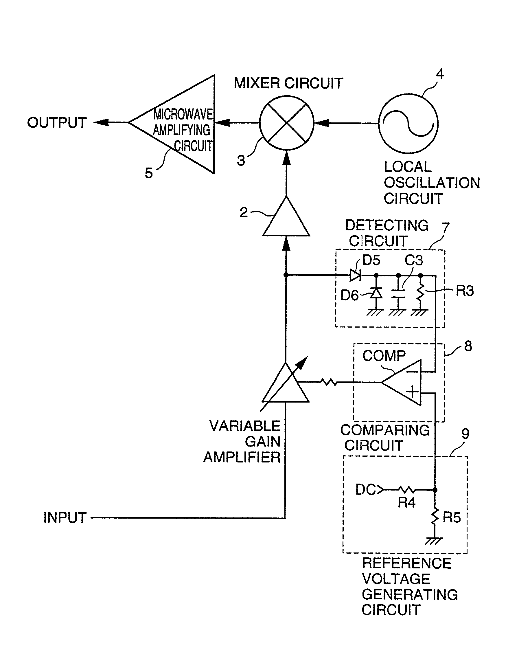
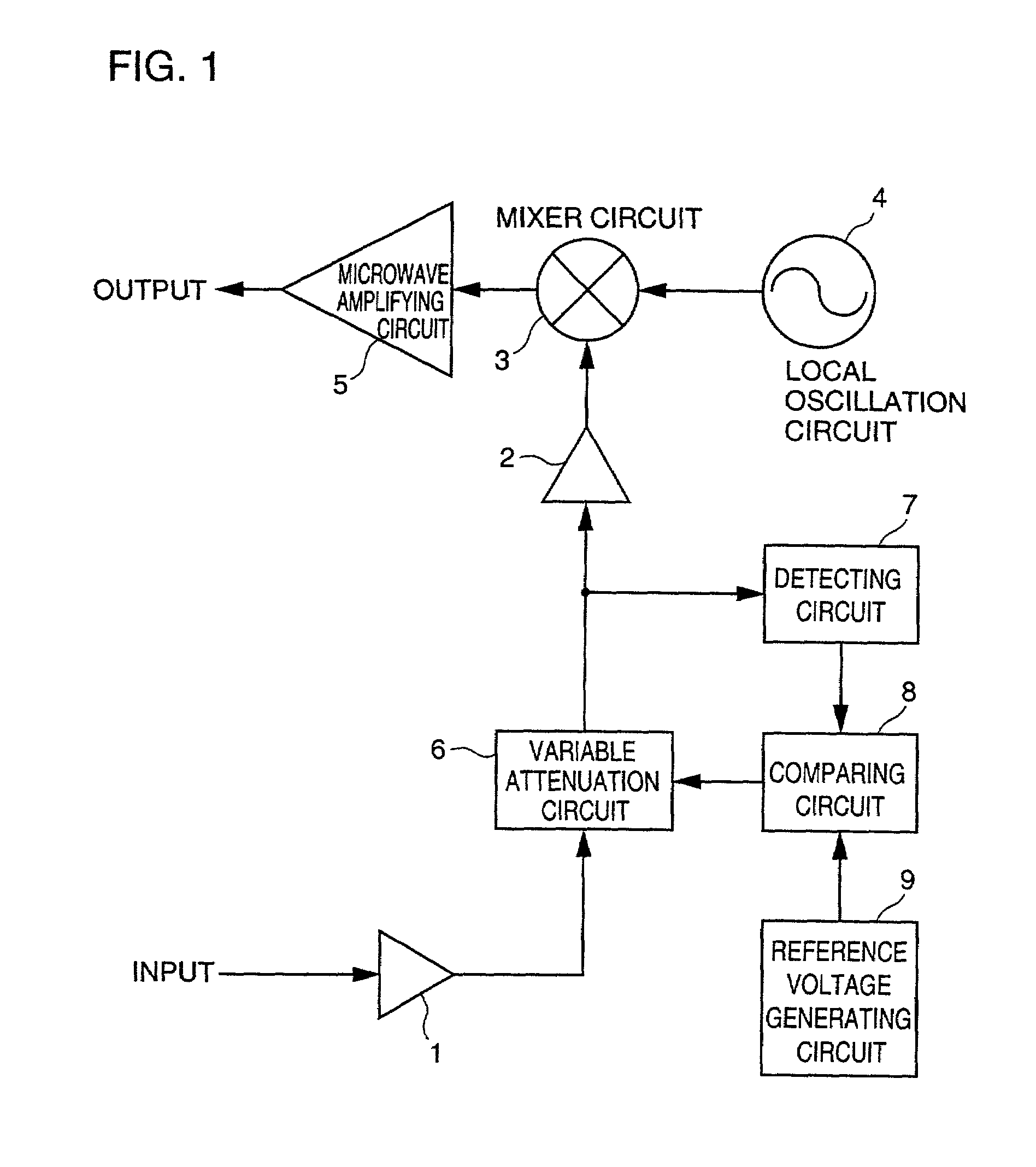
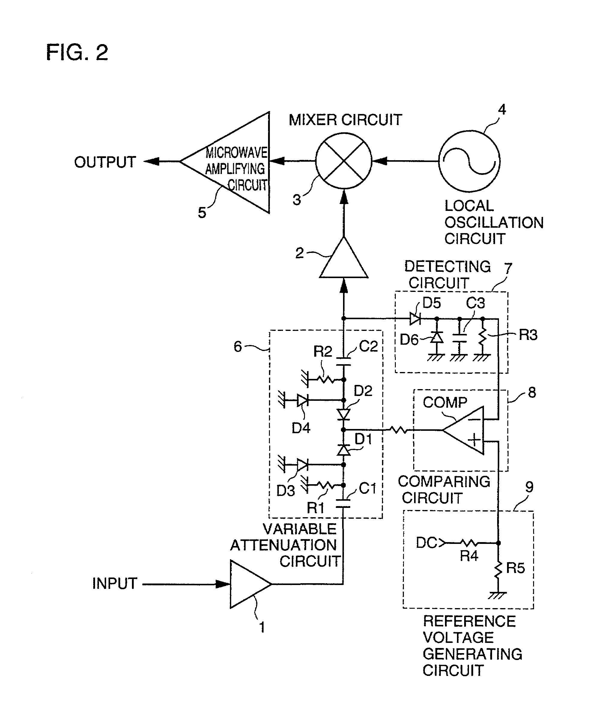
[0031]FIG. 1 is a block diagram of the transmitter in accordance with one embodiment of the present invention. Referring to FIG. 1, an input signal is applied from an indoor unit 20 shown in FIG. 7 through a coaxial cable 21, which has an intermediate frequency signal superposed on a DC voltage. The DC voltage is supplied to a power supply circuit, not shown, only the intermediate frequency signal is applied to and amplified by an amplifier 1 to ensure a prescribed gain, and thereafter it is applied to variable attenuation circuit 6. Variable attenuation circuit 6 changes the amount of level attenuation of the intermediate frequency signal, by a signal from a feedback loop including detecting circuit 7, comparing circuit 8 and reference voltage generating circuit 9.

[0032]The output of variable attenuation circuit 6 is applied to an amplifier 2 as well as to a detecting circuit 7. Detecting circuit 7 rectifies the intermediate frequency signal, converts to a DC voltage and applies th...


PUM


Abstract

An input signal having an intermediate signal superposed on a DC voltage is applied to a variable attenuation circuit through an amplifier. An output of the variable attenuation circuit is detected by a detecting circuit. A DC voltage from the detecting circuit is compared with a reference voltage from a reference voltage generating circuit by a comparing circuit. Based on a comparison output, the amount of attenuation of the variable attenuation circuit is controlled, and after the output of the variable attenuation circuit is amplified by an amplifier, it is mixed with a local oscillation signal from a local oscillation circuit at a mixer circuit, converted to a microwave signal, and transmitted.

Description

BACKGROUND OF THE INVENTION[0001]1. Field of the Invention[0002]The present invention relates to a transmitter. More specifically, the present invention relates to a transmitter for bi-directional microwave communication from general households or small-scale offices to broadcast satellites or communication satellites.[0003]2. Description of the Background Art[0004]The market for radio communication utilizing microwaves has been recently developed dramatically, along with developments of various systems including broadcast satellites and communication satellites. At the same time, the Internet has been developed and digital satellite broadcast has started, ever increasing the demand for bi-directional communication.[0005]For bi-directional communication between a small-scale office or a general home and a broadcasting station, a broadcast satellite or a communication satellite is used. Currently, it is a dominant practice to use the satellite broadcast, as a signal transmission path...

Claims


Application Information

Patent Timeline
IPC IPC(8): H04B1/04H03G1/00H03G3/30
CPCH03G1/0058H03G3/3036
Inventor NITTA, HITOSHI
Owner SHARP KK
Why Eureka
Try Eureka