Method and device for operating a combustion engine

a technology of combustion engine and combustion chamber, which is applied in the direction of electrical control, exhaust treatment electric control, instruments, etc., can solve the problems of uncomplicated plausibility check of two pressure sensors, and achieve the effect of low engine speed

Inactive Publication Date: 2006-10-24
ROBERT BOSCH GMBH
View PDF1 Cites 18 Cited by
  • Summary
  • Abstract
  • Description
  • Claims
  • Application Information

AI Technical Summary

Benefits of technology

[0004]The method and the device according to the present invention for operating a combustion engine provide the advantage that the first pressure sensor and the second pressure sensor are checked for plausibility as a function of at least one modeled variable that characterizes at least one pressure drop in the mass-flow line between the first pressure sensor and the second pressure sensor. In contrast to the conventional monitoring arrangements, this plausibility check in accordance with the present invention also allows the detection of faulty pipe-work of the exhaust branch, leaks in the exhaust branch, as well as sensor drift. In addition, the plausibility check according to the present invention takes the actual loading of a particle filter in the exhaust branch into account. Furthermore, the plausibility check of the present invention is very precise even for operating points with higher engine speeds, and thus provides a very precise check in a generally larger operating range of the combustion engine.
[0005]In accordance with an example embodiment of the present invention, a first value for a pressure differential between the first pressure sensor and the second pressure sensor in the mass-flow line is formed from the difference between the first pressure and the second pressure; a second value for this pressure differential is generated as a function of the at least one modeled variable characterizing at least one pressure drop in the mass-flow line between the first pressure sensor and the second pressure sensor; and the first value for the pressure differential is compared to the second value for the pressure differential and an error is detected if the first value for the pressure differential differs from the second value for the pressure differential by more than a first predefined value. This allows an especially uncomplicated plausibility check of the two pressure sensors via the pressure differential existing between them. Furthermore, an error in the mass-flow line between the first pressure sensor and the second pressure sensor, e.g., a faulty pipe-work or a leak, is able to be detected in an especially simple and reliable manner. In addition, the detection of undesired sensor drift does not require a separate plausibility check of each pressure sensor, but is realizable without much effort by the one-time plausibility check of the pressure differential.
[0006]In accordance with another example embodiment of the present invention, a first value for a third pressure in the mass-flow line between the first pressure sensor and the second pressure sensor is ascertained on the basis of the first pressure and a first modeled variable that characterizes a first pressure drop in the mass-flow line between the first pressure sensor and the second pressure sensor; a second value for the third pressure in the mass-flow line between the first pressure sensor and the second pressure sensor is ascertained on the basis of the second pressure and a second modeled variable that characterizes a second pressure drop in the mass-flow line between the first pressure sensor and the second pressure sensor; and the first value for the third pressure is compared with the second value for the third pressure and an error is detected if the first value for the third pressure deviates from the second value for the third pressure by more than a second predefined value. In this way the plausibility check according to the present invention may be carried out in an especially simple and effortless manner in that a pressure in the form of the third pressure is ascertained at a predefined point or in a predefined region of the mass-flow line between the first pressure sensor and the second pressure sensor, for one, on the basis of the first pressure determined by the first pressure sensor and, for another, on the basis of the second pressure ascertained by the second pressure sensor, and both values for this third pressure are then compared to one another. This approach is able to be realized with a minimum of effort.

Problems solved by technology

This allows an especially uncomplicated plausibility check of the two pressure sensors via the pressure differential existing between them.

Method used


Image

  • Method and device for operating a combustion engine
  • Method and device for operating a combustion engine
  • Method and device for operating a combustion engine

Examples


Embodiment Construction

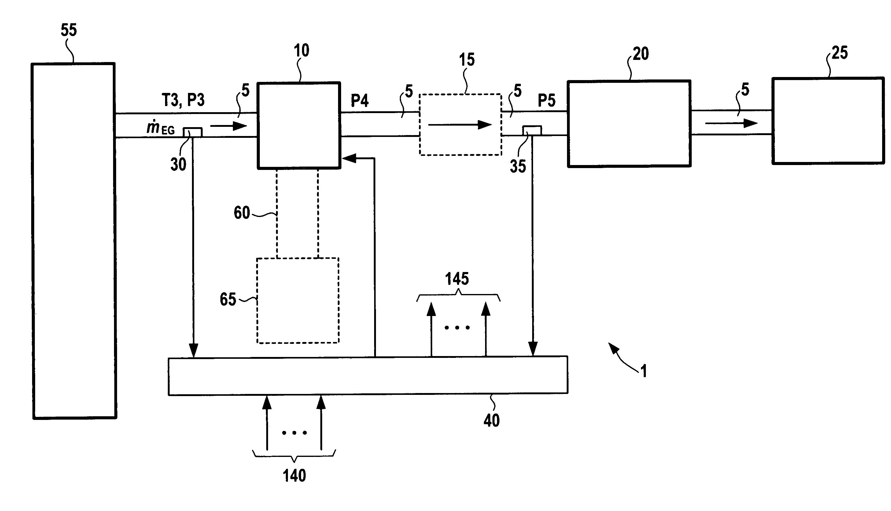
[0016]In FIG. 1, a combustion engine is generally designated by reference numeral 1. In this example, combustion engine 1 is an internal combustion engine such as spark-ignition engine or diesel engine for powering a vehicle. FIG. 1 also shows an exhaust branch 5 of combustion engine 1. This exhaust branch 5 extends from at least one cylinder 55 to a muffler 25. The combustion of air and fuel in the at least one cylinder 55 produces exhaust gas which is expelled from the at least one cylinder 55 into exhaust branch 5 via at least one discharge valve. The resulting exhaust-mass flow is denoted by {dot over (m)}EG in FIG. 1. The flow direction of the exhaust gas in exhaust branch 5 is indicated by arrows in FIG. 1. Arranged in exhaust branch 5, downstream from the at least one cylinder 55, is a first pressure sensor 30, which measures a first pressure p3 of the exhaust gas at this point of exhaust branch 5 and forwards the measuring result to an engine control 40. Arranged downstream ...


PUM


Abstract

A method and a device for operating a combustion engine allow a plausibility check of two pressure sensors in a mass-flow line of the combustion engine in any operating range of the combustion engine. At least one component effecting a pressure drop is provided in the mass-flow line, and a first pressure is measured upstream from the at least one component with the aid of a first pressure sensor, and a second pressure is measured downstream from the at least one component with the aid of a second pressure sensor. The first pressure sensor and the second pressure sensor are checked for plausibility as a function of at least one modeled variable characterizing at least one pressure drop in the mass-flow line between the first pressure sensor and the second pressure sensor.

Description

FIELD OF THE INVENTION[0001]The present invention relates to a method and a device for operating a combustion engine having a mass-flow line and at least one component effecting a pressure drop in the mass-flow line.BACKGROUND INFORMATION[0002]Methods for operating a combustion engine which has a mass-flow line in the form of an exhaust branch and in which at least one component effecting a pressure drop is arranged in the exhaust branch, e.g., a turbine of an exhaust turbocharger, and / or a catalytic converter, are already known. In this context, it is also known that a first pressure can be measured with the aid of a first pressure sensor upstream from the turbine, and a second pressure in the exhaust branch can be measured with the aid of a second pressure sensor downstream from the turbine or downstream from the catalytic converter.[0003]Currently, only limited measures are known to monitor the two pressure sensors in the exhaust branch. At very low engine speeds, or when the eng...

Claims


Application Information

Patent Timeline
Patent Type & Authority Patents(United States)
IPC IPC(8): G06F17/00
CPCF01N3/035F02B39/16F02B77/083F02B77/086F02D41/1448F02D41/222G01L27/007F01N13/009F01N9/002F02B37/00F02B39/00F02D41/187F02D2200/0406F02D2200/0812Y02T10/40
Inventor MOSER, EDUARDEDELMANN, WOLFSARKAR, PRASANTA
Owner ROBERT BOSCH GMBH
Why Eureka
Try Eureka