Methods, systems, circuits, and computer program products for determining polarization of a gas

a hyperpolarized gas and polarization technology, applied in the field of hyperpolarization of gases, can solve the problems of hyperpolarized gas deteriorating or decaying relatively quickly, undesirable decay, and less than satisfactory images in this modality, and achieve the effect of improving reproducibility

Active Publication Date: 2006-10-31
POLAREAN
View PDF2 Cites 4 Cited by
  • Summary
  • Abstract
  • Description
  • Claims
  • Application Information

AI Technical Summary

Benefits of technology

[0014]Systems, circuits, and methods, in accordance with various embodiments of the present invention, may determine polarization with a variability less than about 1% over a temperature range of about 0° C. to about 200° C. Moreover, embodiments of the present invention may provide improved reproducibility, as circuit-to-circuit variability may be less than about 3%.
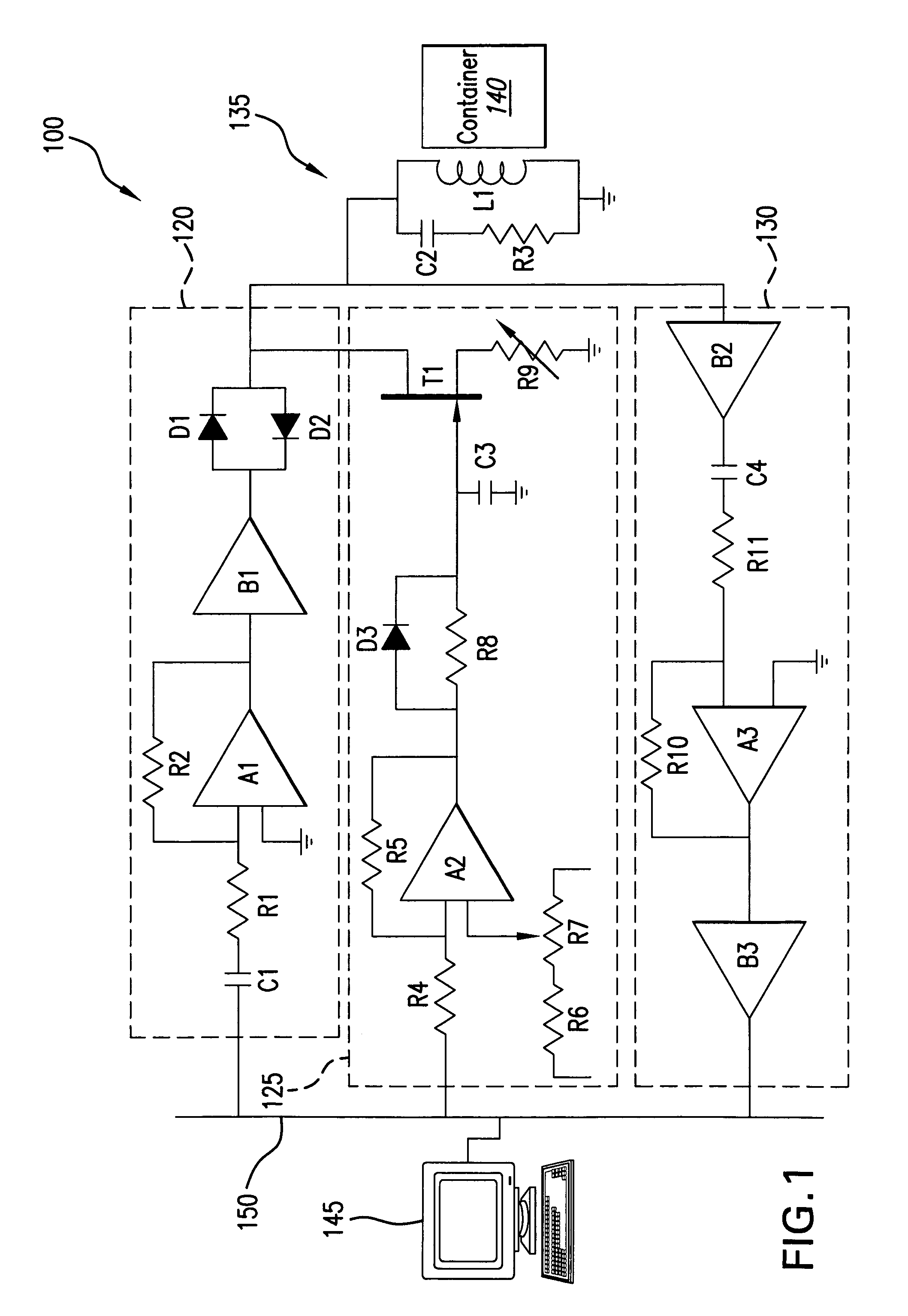
[0015]According to certain embodiments of the present invention, a system for determining polarization of a gas comprises a container that is configured to contain the polarized gas. An oscillator circuit comprises an NMR coil that is positioned adjacent to the optical cell. A pulse generator circuit is configured to generate an electrical pulse that may be transmitted to the optical cell through the NMR coil to excite the polarized gas responsive to a control processor. A Q-reduction circuit that is independent of the pulse generator circuit is configured to reduce oscillations in the oscillator circuit from the transmitted electrical pulse responsive to the control processor. A receive circuit is responsive to an electrical signal that is induced in the oscillator circuit due to the procession of the polarized gas spins. The control processor is configured to determine the polarization of the gas based on the output signal of the receive circuit. Advantageously, by controlling the Q-reduction circuit independently of the pulse generator circuit, the Q-value of the oscillator circuit may be rapidly reduced after the completion of the excitation pulse to reduce ringing in the oscillator circuit due to the excitation pulse.
[0016]In other embodiments, the pulse generator circuit comprises a pair of diodes that are connected in anti-parallel and are placed in parallel with the oscillator circuit upon the conclusion of the excitation pulse to limit a voltage drop across the oscillator circuit to a conduction voltage of one of the pair of diodes. Like the Q-reduction circuit, the diode pair may serve to reduce ringing in the oscillator circuit due to the excitation pulse. In particular embodiments, each of the diodes may have a leakage current associated therewith that is less than about 1 μA, and in particular embodiments may be about 200 nA or less.
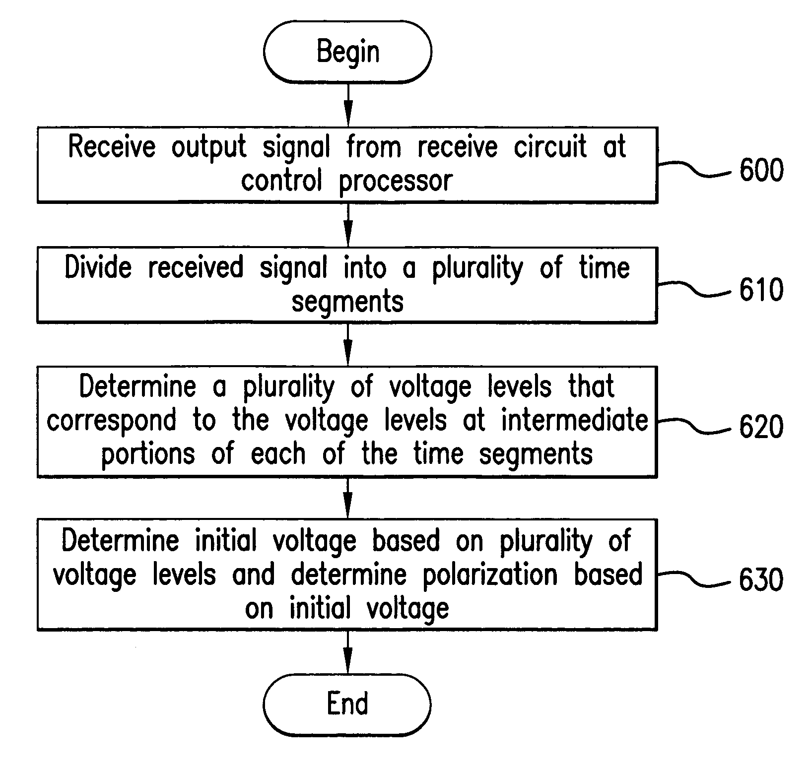
[0019]In still further embodiments of the present invention, a polarimetry circuit for determining polarization of a gas comprises an NMR coil that may be configured to excite a polarized gas and be responsive to an electromagnetic signal generated by the excited, polarized gas. The polarimetry circuit has a polarization measurement variability of less than 2% when the NMR coil is exposed to a temperature in a range of about 0° C. to about 200° C. Such low variability may be promoted by using high quality and / or tightly-held tolerance circuit components in the polarimetry circuit.

Problems solved by technology

It has recently been discovered that polarized inert noble gases can produce improved MRI images of certain areas and regions of the body, which have heretofore produced less than satisfactory images in this modality.
Unfortunately, the polarized state of the gases may be sensitive to handling and environmental conditions and may, undesirably, decay from the polarized state relatively quickly.
Unfortunately, both during and after collection, the hyperpolarized gas can deteriorate or decay relatively quickly (lose its hyperpolarized state) and, therefore, is preferably handled, collected, transported, and stored with care.
Unfortunately, in many production-oriented situations, this technique is not desirable.

Method used


Image

  • Methods, systems, circuits, and computer program products for determining polarization of a gas
  • Methods, systems, circuits, and computer program products for determining polarization of a gas
  • Methods, systems, circuits, and computer program products for determining polarization of a gas

Examples


Embodiment Construction

[0032]While the invention is susceptible to various modifications and alternative forms, specific embodiments thereof are shown by way of example in the drawings and will herein be described in detail. It should be understood, however, that there is no intent to limit the invention to the particular forms disclosed, but on the contrary, the invention is to cover all modifications, equivalents, and alternatives falling within the spirit and scope of the invention as defined by the claims. Like reference numbers signify like elements throughout the description of the figures. In the figures, components, features, and / or layers may be exaggerated for clarity. Certain features or operations may be illustrated in broken line to indicate such feature or operation is optional.

[0033]Various techniques have been used to accumulate and capture polarized gases. For example, U.S. Pat. No. 5,642,625 to Cates et al. describes a high volume hyperpolarizer for spin polarized noble gas and U.S. Pat....


PUM

PropertyMeasurementUnit
wavelengthaaaaaaaaaa
temperatureaaaaaaaaaa
leakage currentaaaaaaaaaa

Abstract

A system for determining polarization of a gas comprises a container that contains the polarized gas. An oscillator circuit comprises an NMR coil that is positioned adjacent to the container. A pulse generator circuit is configured to generate an electrical pulse that may be transmitted to the optical cell through the NMR coil to excite the polarized gas responsive to a control processor. A Q-reduction circuit that is independent of the pulse generator circuit is configured to reduce oscillations in the oscillator circuit from the transmitted electrical pulse responsive to the control processor. A receive circuit is responsive to an electrical signal that is induced in the oscillator circuit due to the electromagnetic excitation of the polarized gas. The control processor is configured to determine the polarization of the gas based on the output signal of the receive circuit. A polarimetry circuit for determining polarization of a gas includes an NMR coil that may be configured to excite a polarized gas and be responsive to an electromagnetic signal generated by the excited, polarized gas. The polarimetry circuit has a reproducible polarization measurement variability of less than 2% when the NMR coil is exposed to a temperature in a range of about 0° C. to about 200° C. Moreover, circuit-to-circuit polarization measurement variability may be less than about 3%.

Description

[0001]This application claims the benefit of Provisional Application No. 60 / 381,610 filed May 17, 2002.FIELD OF THE INVENTION[0002]The present invention relates generally to the field of hyperpolarization of gases, such as noble gases, and, more particularly, to systems, methods, and computer program products for determining the polarization of a hyperpolarized gas.BACKGROUND OF THE INVENTION[0003]It has recently been discovered that polarized inert noble gases can produce improved MRI images of certain areas and regions of the body, which have heretofore produced less than satisfactory images in this modality. Polarized helium-3 (“3He”) and xenon-129 (“129Xe”) have been found to be particularly suited for this purpose. Unfortunately, the polarized state of the gases may be sensitive to handling and environmental conditions and may, undesirably, decay from the polarized state relatively quickly. Because of the sensitivity of a polarized gas and the potential influence on the strengt...

Claims


Application Information

Patent Timeline
Patent Type & Authority Patents(United States)
IPC IPC(8): G01N27/00G01R33/28G01R33/36
CPCG01R33/282G01R33/3628G01R33/3671
Inventor DJUKIC, ZIVKOKADLECEK, STEVENOULS, JOHNNELSON, IANDRIEHUYS, BASTIAAN
Owner POLAREAN
Why Eureka
Try Eureka