Structure for connecting tubular member to fuel tank
- Summary
- Abstract
- Description
- Claims
- Application Information
AI Technical Summary
Benefits of technology
Problems solved by technology
Method used
Image
Examples
Embodiment Construction
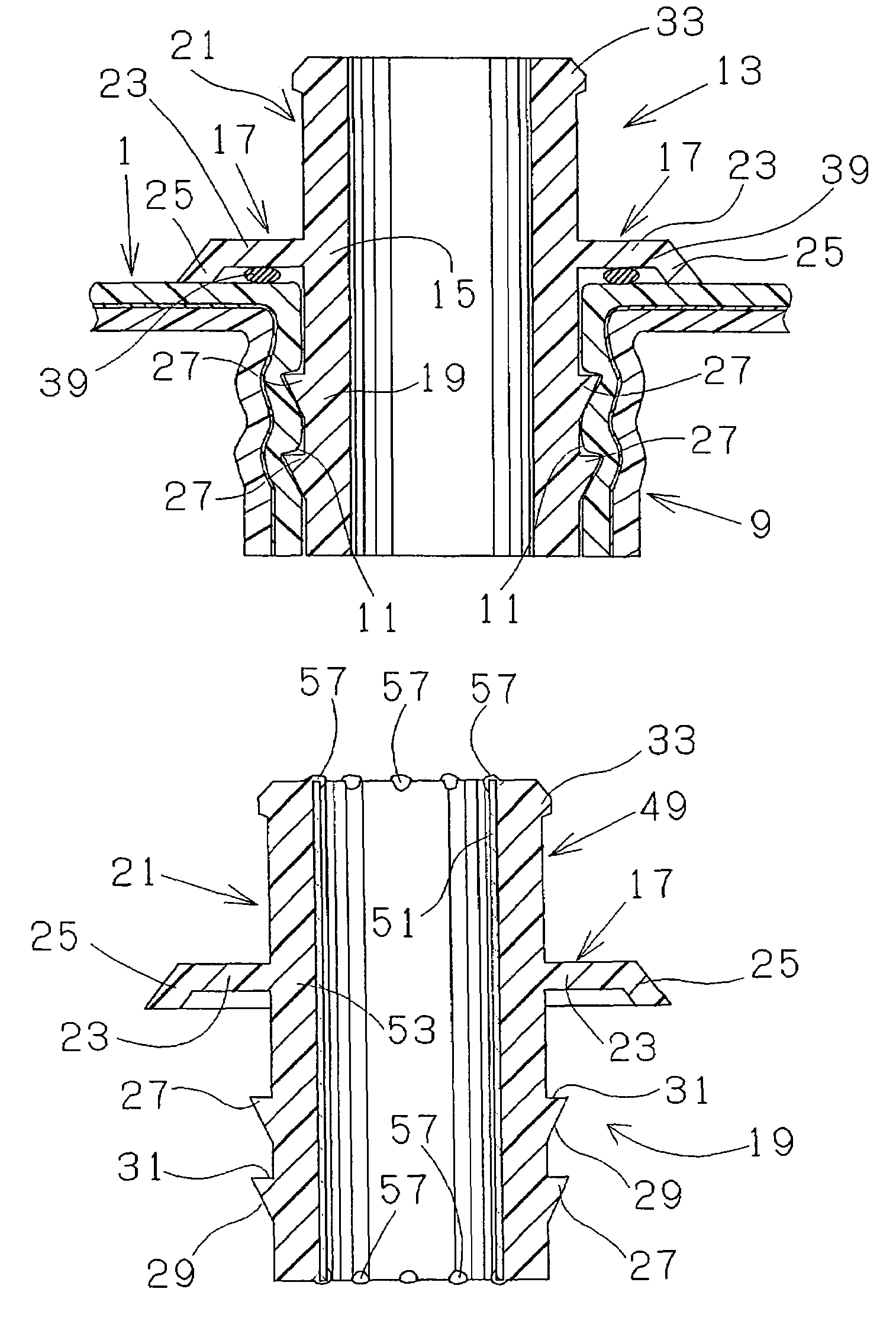
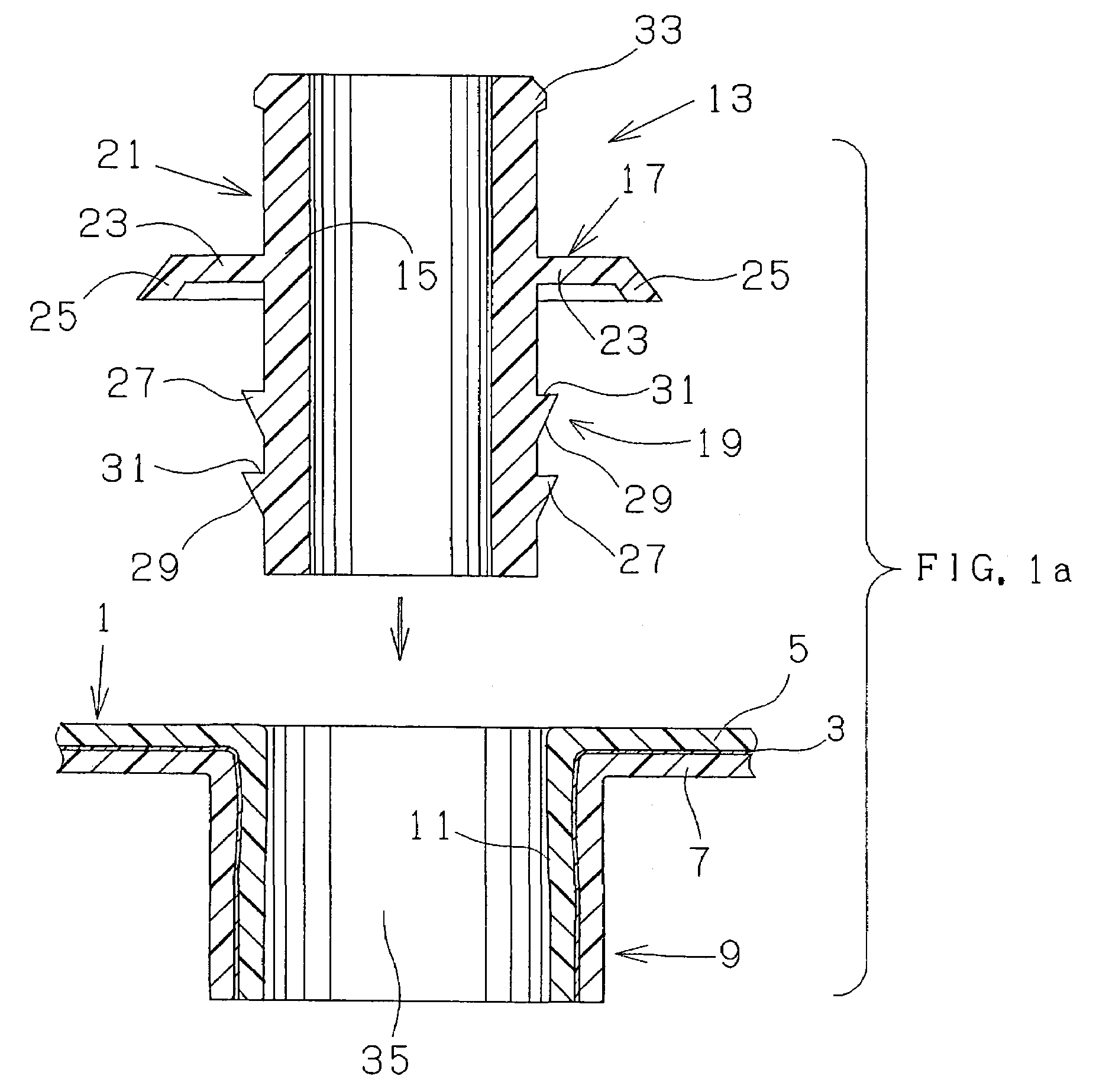
[0031]Referring to FIG. 1 and FIG. 2, it is understood that the present invention is applied for connecting structure between a fuel tank and a filler hose connecting pipe. A fuel tank 1 in this embodiment is blow-molded, and comprises multilayers of approximately 10 mm in thickness, wherein a middle gasoline barrier layer 3 made of PA is joined with material-to-material bond to an outer layer 5 made of HDPE, and to an inner layer 7 made of HDPE. An cylindrical convex portion 9, of which axial opposite ends are open, is formed extending inwardly in a fuel tank 1, so as to provide an opening thereof. The inner peripheral surface 11 of the cylindrical convex portion 9 has sufficient and satisfactory smoothness.
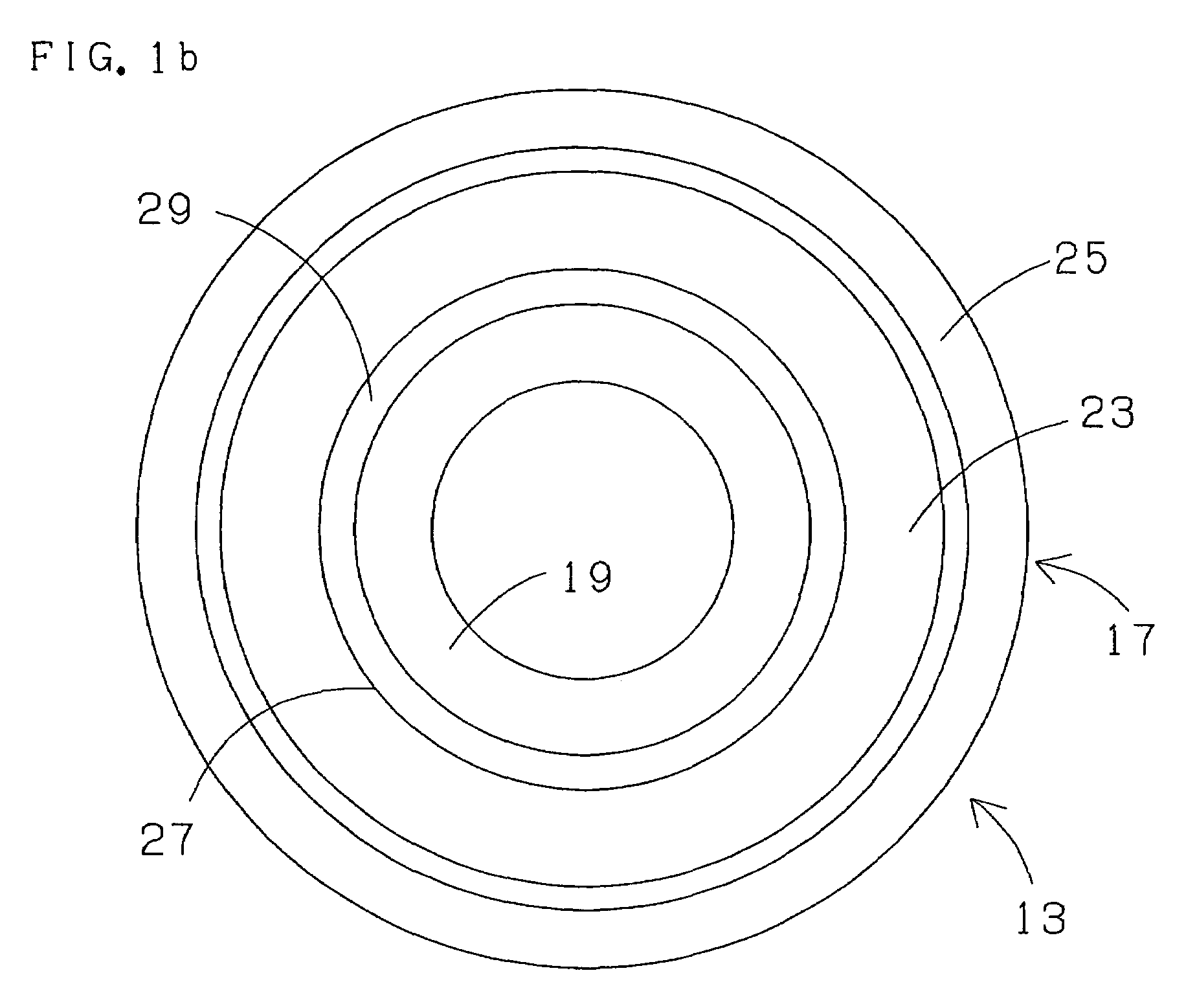
[0032]A filler hose connecting pipe 13 (tubular member) comprises a pipe body 15 and a circumferentially continuous flange 17 integrally formed therewith substantially at the axial (longitudinal) center of the pipe body 15 on the outer peripheral surface thereof. The side in axi...
PUM
 Abstract
Description
Claims
Application Information
 - R&D
- Intellectual Property
- Life Sciences
- Materials
- Tech Scout
- Unparalleled Data Quality
- Higher Quality Content
- 60% Fewer Hallucinations
Browse by: Latest US Patents, China's latest patents, Technical Efficacy Thesaurus, Application Domain, Technology Topic, Popular Technical Reports.
© 2025 PatSnap. All rights reserved.Legal|Privacy policy|Modern Slavery Act Transparency Statement|Sitemap|About US| Contact US: help@patsnap.com


