Ball bats and methods of making same

a bat and bat body technology, applied in the field of ball bats, can solve the problems of not meeting with complete success, not meeting with commercial success, and persistent significant denting of the barrel, so as to increase the batted distance the ball travels, increase the batted strength, and increase the speed of the ball

Inactive Publication Date: 2006-10-31
HONOR LIFE
View PDF10 Cites 30 Cited by
  • Summary
  • Abstract
  • Description
  • Claims
  • Application Information

AI Technical Summary

Benefits of technology

[0010]In such a manner therefore, the rigid (immovable) connection of the handle member's distal end to the distal end of the barrel member and the elastomeric (flexible) connection between the handle member and the proximal end of the barrel thereby allows the handle member to flex substantially across its entire length during ball impact. Stated another way, by means of the present invention, substantial flexure of the handle member occurs between its proximal (knob) end (i.e., the end held by the batsman) and its distal end (i.e., the end which is rigidly connected to the barrel end plug) so as to increase the speed of the ball off the barrel member of the bat when struck thereby increasing the batted distance the ball travels.
[0011]Unlike the limited length and increasing diameter taper associated with conventional handle members of two-piece bats, the handle member of the present invention extends along substantially the entire length of the bat and may be provided with a substantially constant diameter along substantially its entire length, a substantially constant tapered diameter along substantially it's entire length, or varying diameters along substantially it's entire length. As such, the handle member may be made more flexible to produce a flexural response along substantially the entire length of the bat thereby influencing the speed of the ball off the barrel of the bat. In addition, the handle member can be “engineered” for different flexural responses to allow the bat to be tailored to individual hitting styles. This method of using the flexural response of the handle member along substantially the entire length of the bat to influence ball speed off the barrel enables the barrel wall to be thickened (as compared to conventional bat barrels) so as to increase barrel strength to resist denting in aluminum alloys and breakage in composites, without sacrificing bat performance.

Problems solved by technology

Persistent significant problems of barrel denting have occurred for high performance bats having relatively thin-walled barrels.
Bat manufacturers have attempted to solve such problem by careful selection of aluminum alloys, but such attempts have not met with complete success.
Bats constructed of composite materials, such as graphite, fiberglass and / or aramid fiber-reinforced epoxy resins, have not met with much commercial success.
The impact strength of composite materials is much less than that for aluminum and aluminum alloys and thus it has been difficult to match the barrel flex of aluminum without breakage.
As a result, composite material bats have been produced with a stiffer barrel which lacks the performance characteristics of the aluminum bats having flexible thin-walled barrels.

Method used


Image

  • Ball bats and methods of making same
  • Ball bats and methods of making same
  • Ball bats and methods of making same

Examples


Embodiment Construction

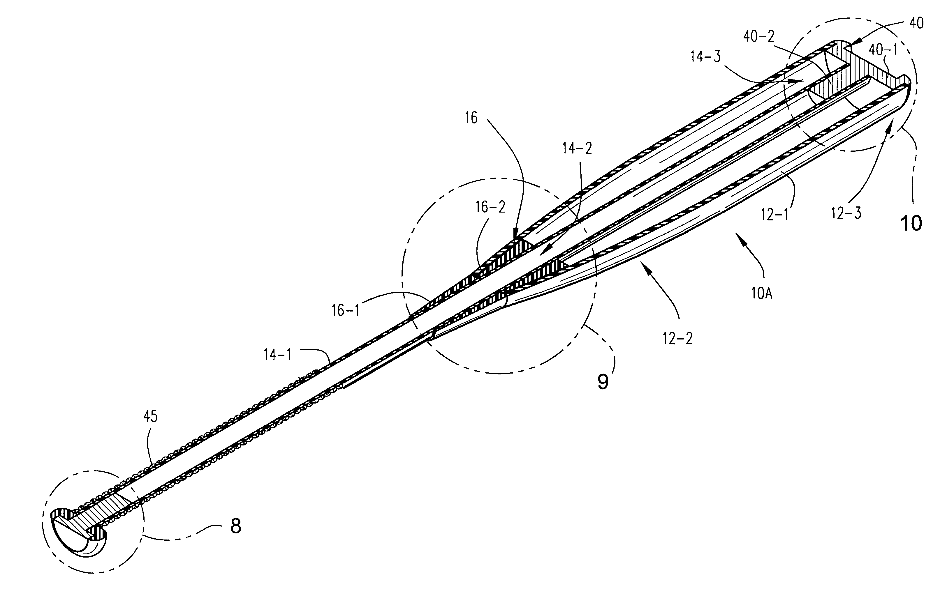
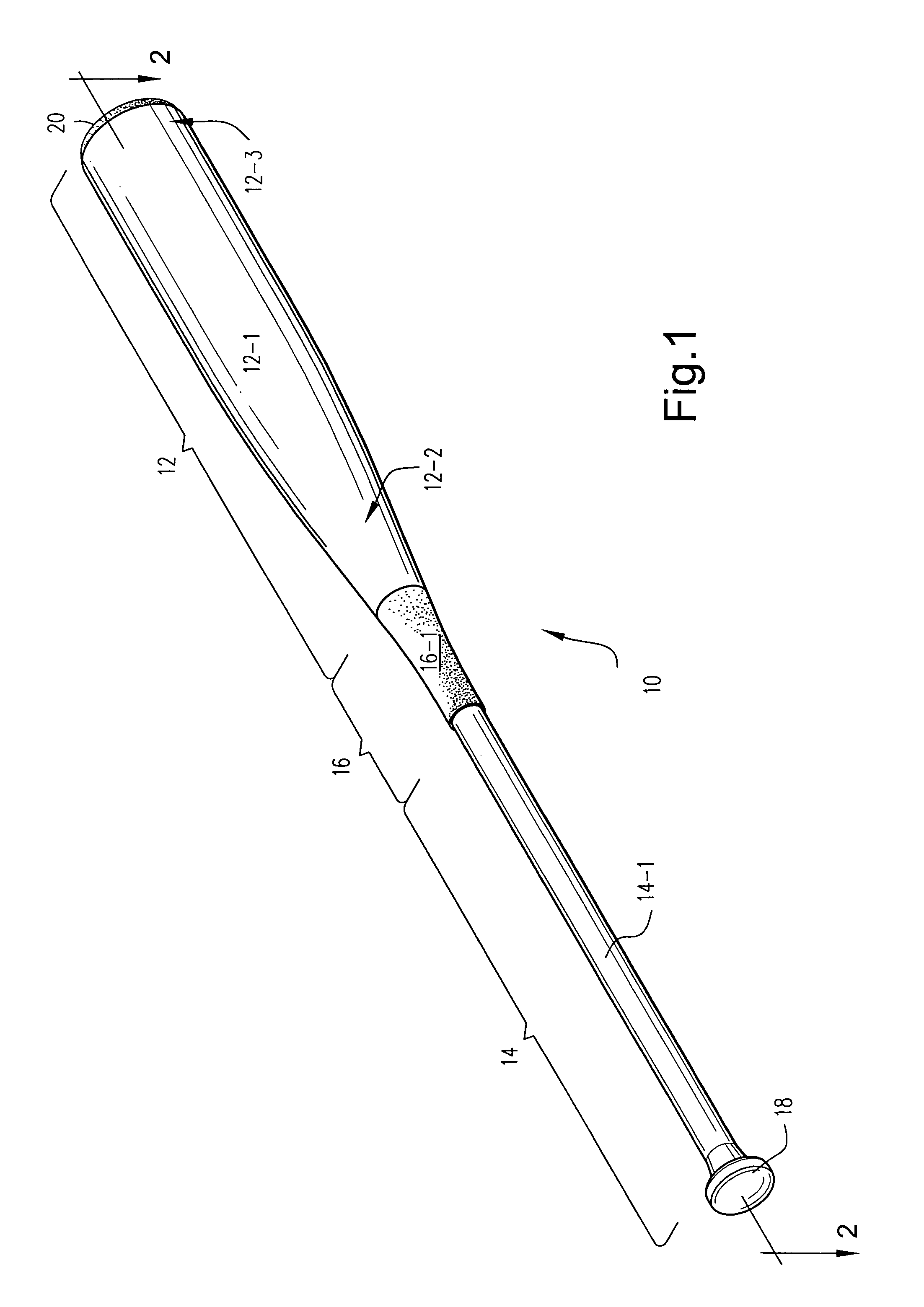
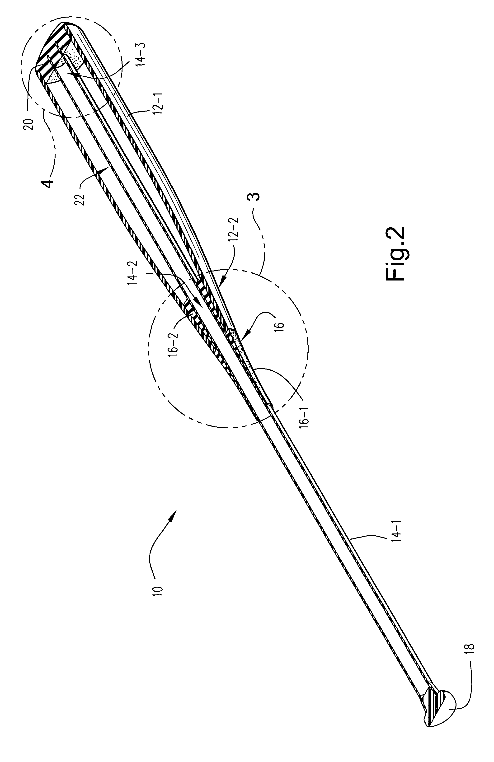
[0024]An exemplary embodiment of a ball bat 10 in accordance with the present invention is depicted in accompanying FIGS. 1 and 2. As shown therein, the bat 10 generally includes a barrel section 12 which includes a cylindrical hollow barrel member 12-1 having a tapered proximal end 12-2 and an open distal end 12-3. A handle section 14 which includes a smaller-diameter tubular handle member 14-1 extends proximally of the barrel section 12. An intermediate region 14-2 (see FIG. 2) of the handle member 14-1 is structurally joined to the proximal end 12-2 of the barrel member 12-1 by means of a proximally located elastomeric connector 16. A proximal region 16-1 of the connector 16 surrounding the intermediate region 14-2 (see FIG. 2) of the handle member 14-1 provides a visibly smooth tapered transition between the larger-diameter barrel member 12-1 and the smaller-diameter handle member 14-1. The visible portion of the handle member 14-1 which proximally extends from the connector 16 ...


PUM


Abstract

Ball bats and methods of making the same are disclosed whereby the handle and barrel members are separate structural components, and whereby the handle member is of sufficient length to extend through the hollow barrel member. The handle member is connected to the barrel member at its proximal and distal ends by proximal and distal connectors. The connection between the handle member at the proximal end of the barrel member is by means of an elastomeric proximal connector. The connection between the handle member and the distal end of the barrel member is accomplished by means of a rigid distal connector. The rigid connection of the handle member's distal end to the distal end of the barrel member and the elastomeric (flexible) connection between the handle member and the proximal end of the barrel thereby allows the handle member to flex substantially across its entire length during ball impact.

Description

CROSS-REFERENCE TO RELATED APPLICATION[0001]The present is a continuation-in-part (CIP) of U.S. Pat. application Ser. No. 10 / 720,693 now abandoned filed on Nov. 25, 2003, entitled “Ball Bats and Methods of Making the Same”, the entire content of which is expressly incorporated hereinto by reference.FIELD OF THE INVENTION[0002]The present invention relates generally to the field of ball bats used in sports games, and to methods of making the same. In especially preferred forms, the present invention is embodied in ball bats whereby the barrel and handle components of the bat are constructed from two separate structural components and united to one another in such a way to promote both ease of manufacture and improved performance.BACKGROUND OF THE INVENTION[0003]The design and construction of non-wood bats has predominately been focussed on aluminum alloys and, to a lesser extent, composite materials such as graphite and glass fibers in an epoxy resin matrix. Historically, these conve...

Claims


Application Information

Patent Timeline
Patent Type & Authority Patents(United States)
IPC IPC(8): A63B59/06
CPCA63B59/06A63B59/0014A63B59/50A63B59/51A63B60/06A63B60/08A63B60/10A63B2102/18
Inventor SOUDERS, ROGERWILLIS, RANDY
Owner HONOR LIFE
Why Eureka
Try Eureka