CPLD with fast logic sharing between function blocks

a function block and logic technology, applied in the field of complex programmable logic devices, can solve the problems of logic buffering, logic incurring delay penalties, logic dividing etc., and achieve the effect of reducing delay penalties resulting from wide operations being divided between multiple logic levels, reducing the size of the operation, and improving resource allocation

Inactive Publication Date: 2006-10-31
XILINX INC
View PDF9 Cites 57 Cited by
  • Summary
  • Abstract
  • Description
  • Claims
  • Application Information

AI Technical Summary

Benefits of technology

[0014]In accordance with the present invention, the operational shortcomings of conventional CPLDs are addressed. In particular, delay penalties resulting from wide operations being divided between multiple logic levels are reduced. Placement of large logic equations can be distributed between multiple function blocks to better allocate resources with minimal added delay, as compared to conventional placement where some functional blocks process large equations while other functional blocks have an abundance of resources available.
[0015]Delays are reduced by providing fast logic sharing between function blocks of the CPLD. Fast logic sharing is created by a feedback path from the output logic macrocell of one function block to the product term inputs of another function block without going through the AIM. The fast feedback path can be provided from the macrocell after the product terms OR gate, and / or after the register of the macrocell. The fast logic sharing avoids the slow AIM for feedback logic, and allows additional resources to be borrowed from other function blocks with practically no delay penalty.
[0016]In particular, the feedback path from the output logic macrocell to a product term input of another functional block eliminates the delays through the AIM. Delay is further reduced with the feedback path bypassing both the AIM and macrocell register. Delay terms for the overall system operation frequency, fSYSTEM, are eliminated showing an increased operation frequency relative to conventional CPLDs.
[0017]With a fast feedback path between functional blocks reducing delay, in accordance with the present invention, the following advantages occur: (1) overall operation frequency is increased with multiple logic levels; (2) large equations can be divided between logic levels with minimum delay; (3) pin locking can be provided with software using logic buffering to create multiple logic levels with minimal additional delay; and (4) device resource utilization is significantly improved, thus, avoiding the need for a larger CPLD.

Problems solved by technology

The procedure incurs a delay penalty.
If the associated logic exceeds the available function block resources, such as macrocells, product terms, and the function block inputs, the software cannot map the logic to the macrocell.
Logic buffering works, but incurs some penalties.
This additional delay again reduces the maximum system frequency.
For logic buffering used to fit a design to a specific CPLD, the desire for a speed mode as opposed to a minimal density mode makes it more difficult to keep pin locking.

Method used


Image

  • CPLD with fast logic sharing between function blocks
  • CPLD with fast logic sharing between function blocks
  • CPLD with fast logic sharing between function blocks

Examples


Embodiment Construction

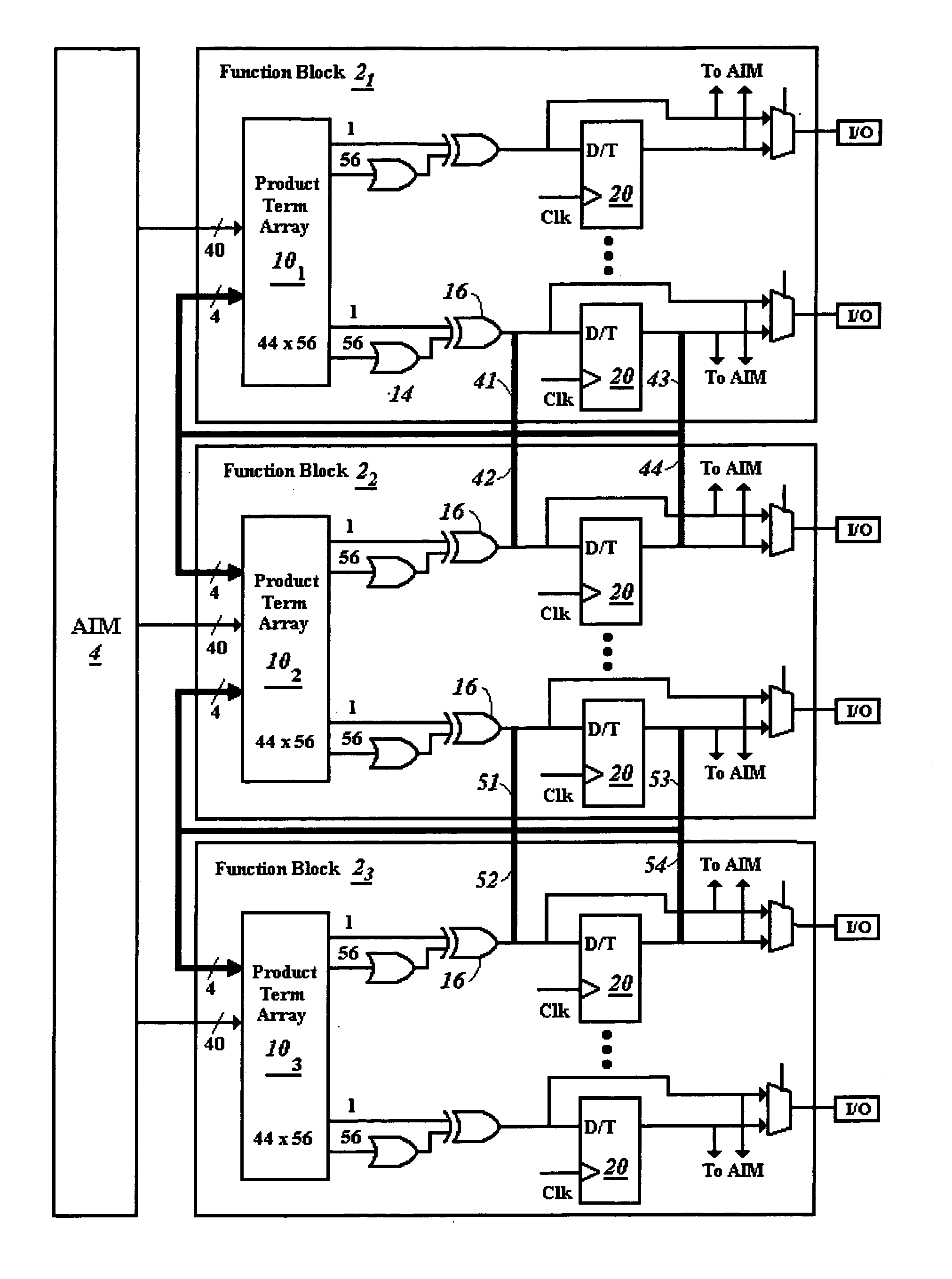
[0027]FIG. 5 illustrates the fast logic feedback paths 41–44 and 51–54 among functional blocks 21-3 of a PLD provided in accordance with the present invention. The logic sharing is implemented by connecting shared generated logic directly to the input of the product term arrays in different function blocks 21-3 using connections 41–44 and 51–54. In particular, the fast logic feedback paths bypass the AIM 4.

[0028]The shared connection feedback points may be from a number of different logic resources within a function block. For example the feedback point may be from the output of the XOR gate, such as XOR outputs 41 and 42, within a macrocell, or the output of the register, such register outputs 43 and 44, within a macrocell. The feedback may further be provided from both the output of the XOR gate 16 and the register 20. Although feedback connections after the XOR gate 16 and register 20 are illustrated, other connection points may likewise be used, such as after the OR gate 14, and...


PUM


Abstract

Fast logic sharing is created using a feedback path from the output logic macrocell of one functional block to the product term inputs of another function block without going through an advanced interconnect matrix (AIM). The fast feedback path may be provided from the macrocell after the product terms XOR gate without registering, and / or after the register in the macrocell. The fast logic sharing avoids the slow AIM for feedback logic, and allows additional resources to be borrowed from other function blocks with a limited delay penalty. In particular, delay penalties resulting from dividing wide operations requiring multiple product terms between the product terms of multiple functional blocks are significantly reduced.

Description

TECHNICAL FIELD[0001]The present invention relates to complex programmable logic devices (CPLDs). More particularly, the present invention relates to architecture of CPLDs, the CPLDs including logic function blocks interconnected by an advanced interconnect matrix (AIM), for interconnecting logic between function blocks interconnected by the AIM.RELATED ART[0002]FIG. 1 is a block diagram illustrating components of a typical CPLD. The typical CPLD architecture interconnects multiple function blocks 2 made up of components found on smaller sized PLDs using the AIM 4. Each function block 2 internally includes logic forming product term arrays 10, with outputs of the product term arrays 10 provided to macrocells (MC) 6. Outputs of the macrocells 6 are either provided through the AIM 4 to an output of function block 2 through an input / output (I / O) block 8, or on a feedback path through AIM 4 to the inputs of product term array 10 within the same functional block 2, or through the AIM 4 t...

Claims


Application Information

Patent Timeline
Patent Type & Authority Patents(United States)
IPC IPC(8): G06F7/38H01L25/00H03K19/173H03K19/177
CPCH03K19/17736
Inventor JANG, TETSESOE, SOREN T.LIEN, SCOTT TE-SHENG
Owner XILINX INC
Why Eureka
Try Eureka