
Power supply generating circuit, display apparatus, and portable terminal device

a technology of power supply and generating circuit, which is applied in the direction of power management, process and machine control, instruments, etc., can solve the problems of high power consumption loss, difficult to provide compact and low-cost portable terminal devices incorporating liquid crystal display devices, and increase the complexity of the overall structure of the liquid crystal display devices and the cost of the apparatus, so as to reduce the overall power consumption loss, increase efficiency, and reduce the effect of power consumption loss

Active Publication Date: 2006-10-31
JAPAN DISPLAY WEST
View PDF8 Cites 38 Cited by
  • Summary
  • Abstract
  • Description
  • Claims
  • Application Information

AI Technical Summary

Benefits of technology

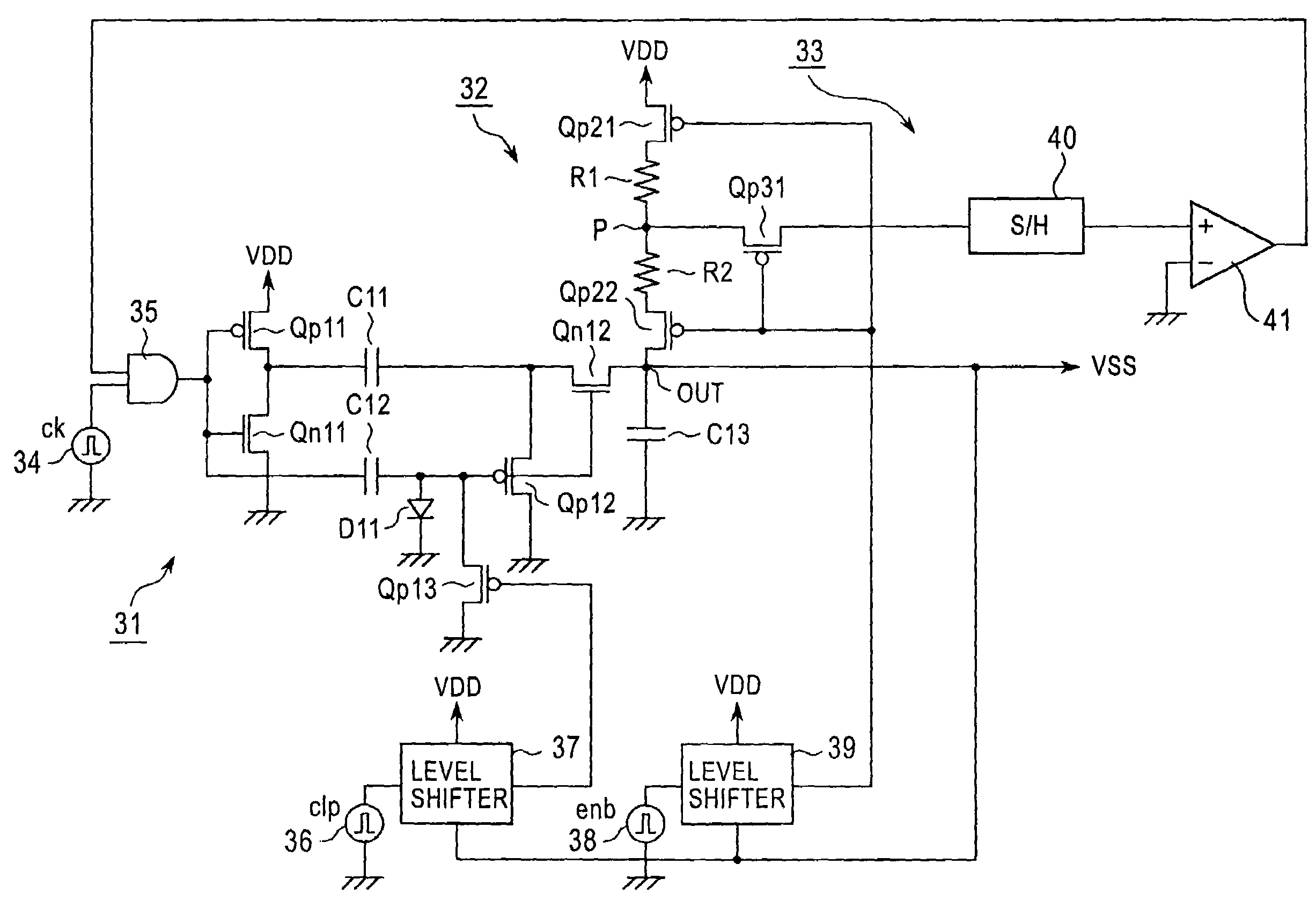
[0009]According to the present invention, at least one of a voltage dividing circuit for dividing a circuit output voltage and a comparator is active only for a certain period of time, thus reducing the power consumption loss caused by a constant current flow in voltage-divider resistors or the comparator to increase the efficiency. Therefore, the power consumption of the overall apparatus can be reduced.

Problems solved by technology

A power supply generating circuit provided for each of the power supply voltages would increase the complexity of the overall structure of the liquid crystal display apparatus and the cost of the apparatus, thus making it difficult to provide a compact and low-cost portable terminal device incorporating the liquid crystal display apparatus.
However, a liquid crystal display apparatus for this application is designed such that, typically, a DC-DC converter having the regulation ability causes a current to flow in voltage-divider resistors for use in voltage comparison at any time other than the time of voltage comparison during a regulation operation, resulting in high power-consumption loss and low efficiency.

Method used


Image

  • Power supply generating circuit, display apparatus, and portable terminal device
  • Power supply generating circuit, display apparatus, and portable terminal device
  • Power supply generating circuit, display apparatus, and portable terminal device

Examples


Embodiment Construction

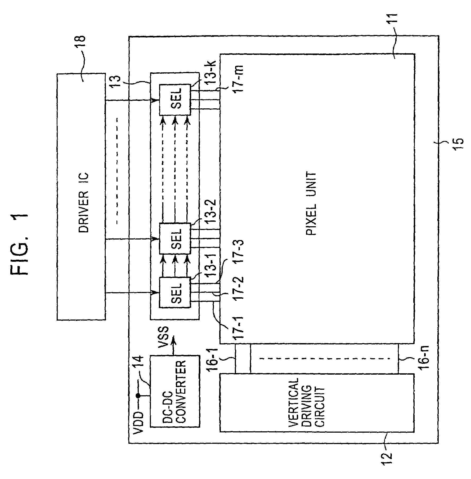
[0019]An embodiment of the present invention is described in detail below with reference to the drawings. FIG. 1 is a block diagram schematically showing the overall structure of a liquid crystal display apparatus according to an embodiment of the present invention.

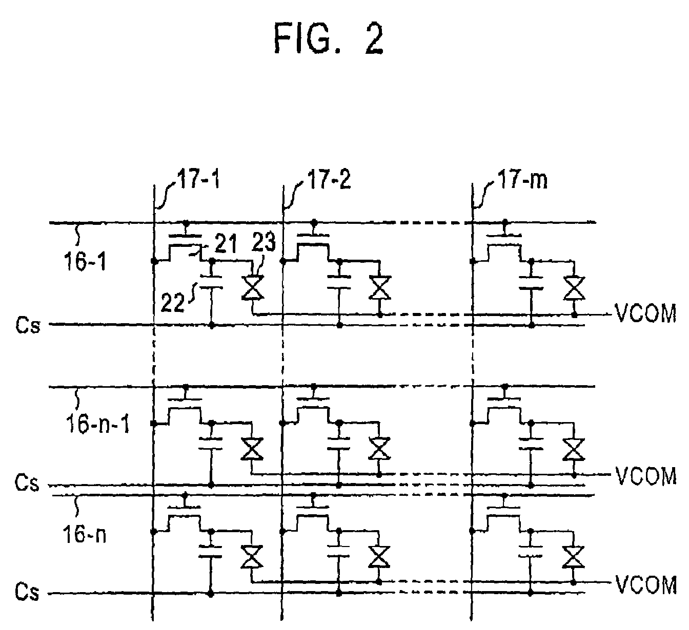
[0020]As is apparent from FIG. 1, the liquid crystal display apparatus according to this embodiment includes a pixel unit 11 having an array of pixel circuits including liquid crystal cells, a vertical driving circuit 12 for selectively driving the pixel circuits of the pixel unit 11 in units of rows, a selector circuit 13 for selectively supplying an image signal to the pixels in the row selectively driven by the vertical driving circuit 12 under the drive control according to a selector driving method, and a DC-DC converter 14 serving as a power supply generating circuit for generating, for example, a negative power supply voltage VSS based on an internal circuit power supply voltage VDD.

[0021]The liquid crystal display...


PUM


Abstract

A power supply generating circuit, a display apparatus incorporating the same, and a portable terminal device using the display apparatus as an output display unit are provided. In a DC-DC converter having a charge pump circuit (31), a voltage dividing circuit (32), and a regulation circuit (33), p-channel MOS transistors (Qp21, Qp22, Qp31) are turned on / off based on an enable pulse enb to make the voltage dividing circuit (32) and a comparator (41) active only for a period of regulation time and inactive otherwise. This can cause a current to flow in voltage-divider resistors (R1, R2) and the comparator (41) only for a certain period of time required for the regulation operation, thus reducing the power consumption loss caused by a constant current flow in the voltage-divider resistors (R1, R2) and the comparator (41).

Description

[0001]This application claims priority to Japanese Patent Application Number JP2001-366340, filed Nov. 30, 2001, which is incorporated herein by reference.TECHNICAL FIELD[0002]The present invention relates to a power supply generating circuit, a display apparatus, and a portable terminal device. More particularly, the present invention relates to a power supply generating circuit for, based on a power supply voltage having a given voltage value, generating a power supply voltage having a different voltage value therefrom, a display apparatus incorporating the power supply generating circuit, and a portable terminal device using the display apparatus as an output display unit.BACKGROUND ART[0003]Recently, portable terminal devices such as cellular telephones and PDAs (Personal Digital Assistants) have become increasingly widespread. One factor that has contributed to such rapid widespread adoption of portable terminal devices is a display device incorporated therein as an output disp...

Claims


Application Information

Patent Timeline
IPC IPC(8): G09G5/00G09G3/36G09G3/20H02M3/07H04B7/26H04W52/02H04W88/02
CPCH02M3/07H02M3/073G09G3/36G09G2330/022H04B1/40
Inventor TOYOZAWA, NOBORUNAKAJIMA, YOSHIHARU
Owner JAPAN DISPLAY WEST
Learn More