IPS type liquid crystal display with protrusive electrodes

a liquid crystal display and electrode technology, applied in non-linear optics, instruments, optics, etc., can solve the problems of reducing the clarity of the display of the liquid crystal display, the electric field in the liquid crystal layer is not ideal parallel electric field, and the narrow viewing angle of the liquid crystal molecules, etc., to achieve good picture quality, low driving voltage, and high aperture ratio

Inactive Publication Date: 2006-10-31
INNOLUX CORP
View PDF6 Cites 17 Cited by
  • Summary
  • Abstract
  • Description
  • Claims
  • Application Information

AI Technical Summary

Benefits of technology

[0009]An object of the present invention is to provide an IPS liquid crystal display which enables good picture quality, a low driving voltage, and / or a high aperture ratio.
[0011]When a voltage is applied to the common and pixel electrodes, an electric field is generated by the protrusive electrodes. The protrusive electrodes generate a more uniform parallel electric field, compared with a conventional LCD that has flat electrodes disposed below a liquid crystal layer and which generates an arch-shaped driving electric field. Accordingly, liquid crystal molecules in the liquid crystal layer of the present invention have more uniform orientations, and thus provide a better picture quality. In addition, the protrusive electrodes can generate a stronger electric field compared with the flat electrodes of the prior art when a same voltage is applied. Therefore the LCD of the present invention needs a lower driving voltage, and / or can provide larger spaces between adjacent electrodes. This yields lower power consumption and / or a higher aperture ratio.

Problems solved by technology

A conventional liquid crystal display which employs twisted nematic control of liquid crystal molecules is burdened with the inherent problem of a narrow viewing angle.
However, the electric field in the liquid crystal layer is not an ideal parallel electric field.
This variation in orientations reduces the clarity of the display of the LCD 1; that is, the picture quality is lowered.
This results in high power consumption and / or a low aperture ratio.

Method used


Image

  • IPS type liquid crystal display with protrusive electrodes
  • IPS type liquid crystal display with protrusive electrodes
  • IPS type liquid crystal display with protrusive electrodes

Examples


Embodiment Construction

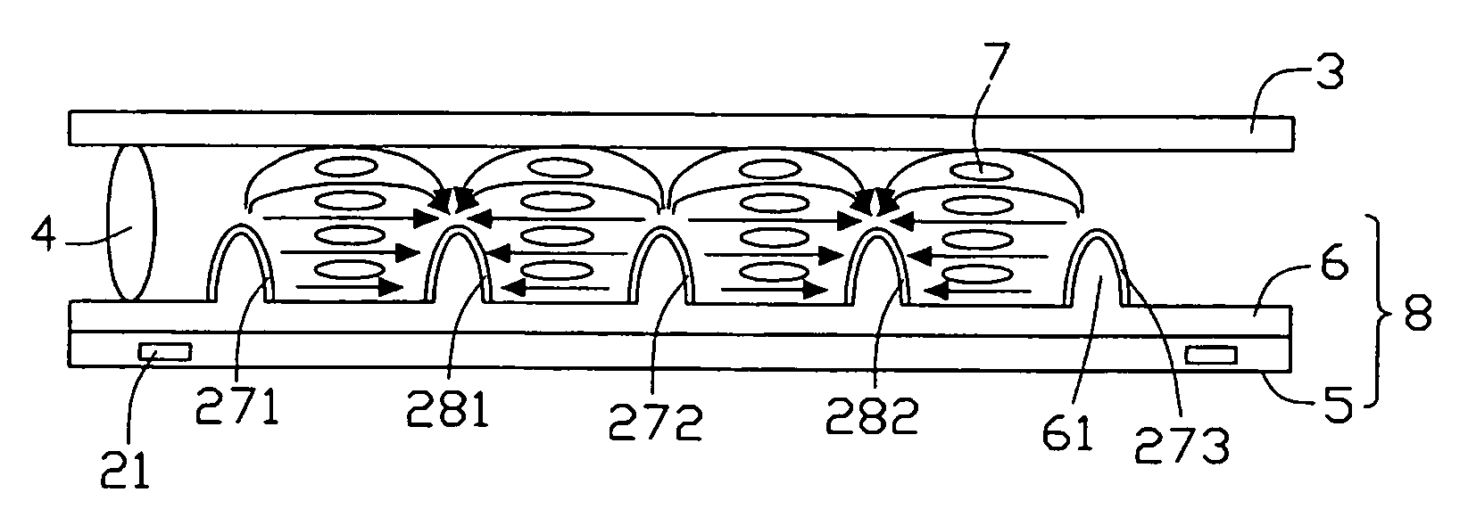
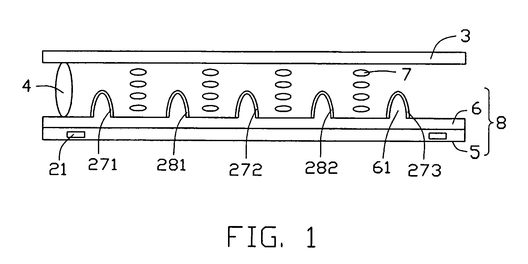
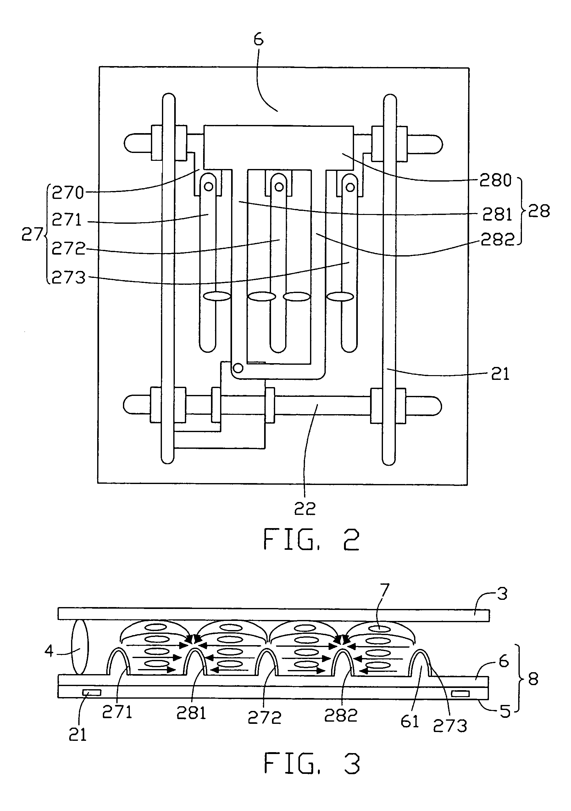
[0019]Referring to FIG. 1 and FIG. 2, an in-plane switching liquid crystal display (IPS LCD) according to the preferred embodiment of the present invention comprises a color filter substrate 3, a TFT substrate 8, a liquid crystal layer 7 comprising bar-shaped liquid crystal molecules (not labeled) interposed between the color filter and TFT substrates 3, 8, and spacers 4 disposed between the color filter and TFT substrates 3, 8 for supporting the two substrates 3, 8 and maintaining a space therebetween.

[0020]The TFT substrate 8 comprises a TFT plate 5, a protrusion layer 6 comprising a plurality of protrusion portions 61 protruding into the liquid crystal layer 7, and an electrode matrix. The protrusion portions 61 extend up to a level about halfway between the color filter and TFT substrates 3, 8. The electrode matrix comprises transversely disposed gate lines 22, longitudinally disposed data lines 21, switching elements (not labeled), a plurality of common electrodes 27, and a plu...


PUM

PropertyMeasurementUnit
distanceaaaaaaaaaa
electric fieldaaaaaaaaaa
strengthaaaaaaaaaa

Abstract

An IPS (in-plane switching) liquid crystal display has a color filter substrate (3), a TFT (thin film transistor) substrate (8), and a liquid crystal layer (7) interposed therebetween. The TFT substrate includes a TFT plate (5), a protrusion layer (6), and an electrode matrix. The electrode matrix includes a plurality of transversely disposed gate lines (22), a plurality of longitudinally disposed data lines (21), switching elements, a plurality of common electrodes (27), and a plurality of pixel electrodes (28). The protrusion layer has a plurality of protrusion portions (61). The common and pixel electrodes are formed on the protrusion portions in one-to-one correspondence to provide an array of protrusive electrodes that generate a strong and highly uniform parallel electric field. This provides better picture quality, and can lower power consumption and / or yield a higher aperture ratio.

Description

BACKGROUND OF THE INVENTION[0001]1. Field of the Invention[0002]The present invention relates to an in-plane switching liquid crystal display (IPS LCD).[0003]2. Description of Prior Art[0004]A conventional liquid crystal display which employs twisted nematic control of liquid crystal molecules is burdened with the inherent problem of a narrow viewing angle. In order to overcome this problem, IPS liquid crystal displays have been developed. In such LCDs, an electric field applied to the liquid crystal molecules is generated in a plane parallel to a main substrate of the LCD.[0005]FIG. 4 is a schematic, side cross-sectional view of a conventional IPS liquid crystal display 1. FIG. 5 is a top elevation of the LCD 1 corresponding to FIG. 4. As illustrated, the LCD 1 comprises a color filter substrate 10, a TFT (thin film transistor) substrate 12, a liquid crystal layer 14 interposed between the substrates 10, 12, and spacers 20 disposed between the substrates 10, 12 for supporting the L...

Claims


Application Information

Patent Timeline
Patent Type & Authority Patents(United States)
IPC IPC(8): G02F1/1337G02F1/1339G02F1/1343G02F1/1333
CPCG02F1/133707G02F1/134363G02F2201/40G02F2201/12
Inventor HSIEH, TSAU-HUAPANG, JIA-PANGCHEN, CHEUH-JU
Owner INNOLUX CORP
Why Eureka
Try Eureka