
Telescope accessory

a technology for telescopes and accessories, applied in the field of telescope accessories, can solve the problems of not being able to observe a planet previously, faint objects located on or near these spikes are difficult to detect, and the contrast of the final image produced by the telescope is degraded

Active Publication Date: 2006-10-31
AMERICAN MUSEUM OF NATURAL HISTORY
View PDF3 Cites 7 Cited by
  • Summary
  • Abstract
  • Description
  • Claims
  • Application Information

AI Technical Summary

Benefits of technology

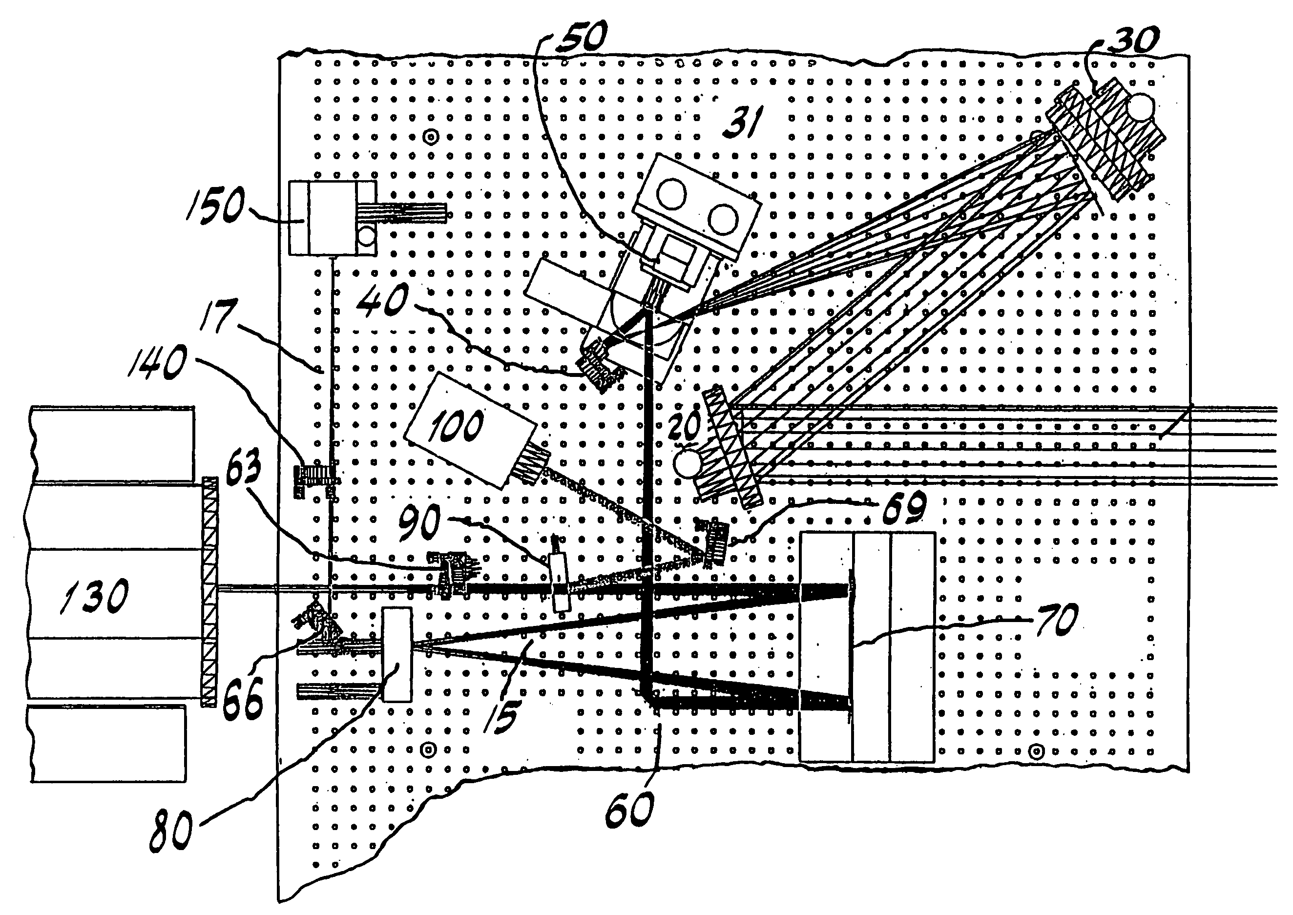
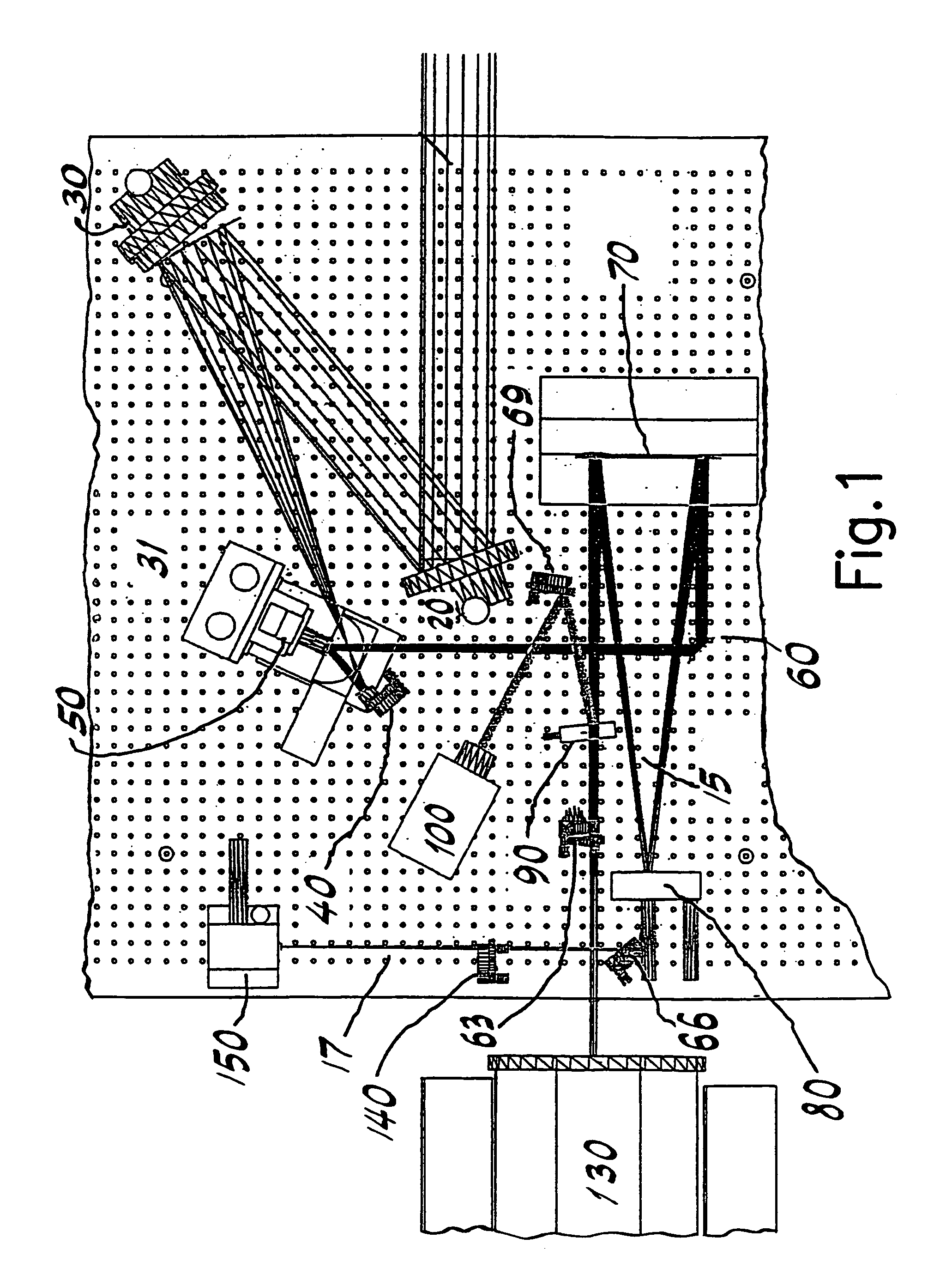
[0005]In a first embodiment according to the present invention, a coronagraph for detecting reflective bodies external to a light source is provided. The present invention according to the first embodiment comprises a first mirror for directing a beam of light onto an occulting mask. The first mirror is adjustable based on a data from a fiber optic sensor or a first sensor. An occulting mask for separating the beam into a first and second portion is also provided. The occulting mask directs the first portion onto a fiber optic sensor and the second portion onto a Lyot stop. The occulting mask is adjustable based on data from the second sensor. The Lyot stop separates the second portion of the beam into a third and fourth portion. The Lyot stop directs the third portion of the beam onto the second sensor and the fourth portion of the beam onto a camera for detecting one or more reflective bodies external to a light source.
[0006]In a second embodiment of the present invention, a method for detecting reflective bodies external to a light source is provided. A first portion of a beam of light is detected at a fiber optic sensor after the beam has passed through an occulting mask. Based on a data from the fiber optic sensor, a first mirror or an occulting mask is adjusted. A s...

Problems solved by technology

These elements scatter a substantial amount of light and degrade the contrast of the final image produced by the telescope.
Faint objects located on or near these spikes are very difficult to detect.
Without the occulting spot, light from the star would saturate the detection device, and the optical elements would fill the background with scattered light, as well as produce spurious reflections.
However, it has not been previously possible to observe a planet which is orbiting a star (other than the sun) with a coronagraph.
It has also not been possible to observe microsatellites placed near larger satellites.

Method used


Image

  • Telescope accessory
  • Telescope accessory
  • Telescope accessory

Examples


Embodiment Construction

[0029]In an embodiment according to the present invention, a beam of light from a body of interest (e.g., an extrasolar solar system or a satellite cluster) is separated into a first portion and a second portion by an occulting mask. The beam is directed onto the occulting mask by a plurality of mirrors both flat and parabolic. The first portion of the beam impinges a fiber head and the second portion impinges a Lyot stop. The Lyot stop reflects some of the light from the second portion of the beam onto an imaging camera and allows the remainder of the light to pass through. The light that passes through the Lyot stop impinges an IR camera, where bodies external to a light source are detected. Such external bodies can be, but are not limited to, planets orbiting an extrasolar star or smaller satellites orbiting a larger satellite. Based on the data received by the fiber head and / or the imaging camera, the Lyot stop, the occulting mask, and / or the mirrors are adjusted to improve the ...


PUM


Abstract

In an embodiment according to the present invention, a coronagraph for detecting reflective bodies external to a light source is provided. A first mirror for directing a beam of light onto an occulting mask is adjusted based on a data from a fiber optic sensor or a second sensor. An occulting mask for separating the beam into a first and second portion directs the first portion onto a fiber optic sensor and the second portion onto a Lyot stop. The occulting mask is adjustable based on data from the second sensor. The Lyot stop separates the second portion of the beam into a third and fourth portion. The Lyot stop also directs the third portion of the beam onto the second sensor and the fourth portion of the beam onto a camera for detecting one or more reflective bodies external to a light source.

Description

BACKGROUND INFORMATION[0001]Astronomers can image the environments of nearby stars on scales comparable to our own solar system. New classes of astrophysical objects have been discovered including circumstellar debris disks, brown dwarfs, and super-Jupiter mass planets. These discoveries have galvanized intense public interest in science and technology and have led to profound new insights into the formation and evolution of planetary systems such as our own. Among the key technologies that have enabled this are adaptive optics (AO) and coronagraphy, both of which deliver the high image contrast for the discovery and characterization of faint stellar companions and circumstellar disks in the solar neighborhood. The highest order AO system available to the astronomical community in the United States is the Air Force Advanced Electro-Optical System (AEOS), located at the Air Force Research Laboratory's (AFRL) Maui Optical Site (AMOS) on Maui.[0002]AEOS is a 3.67-meter telescope owned ...

Claims


Application Information

Patent Timeline
IPC IPC(8): G01N21/55G01N21/47G01J5/02G01J1/42G01N21/01G02B5/00G02B23/00
CPCG01J1/4228G02B5/005G02B23/00G01J1/0403G01J1/0437G01J1/0444
Inventor OPPENHEIMER, BEN R.SHARA, MICHAEL M.
Owner AMERICAN MUSEUM OF NATURAL HISTORY
Learn More