
Real-time measurement of ultrashort laser pulses

a laser pulse and ultrashort technology, applied in the field of real-time measurement of ultrashort laser pulses, can solve the problems of insufficient speed of modern electronics to allow direct time resolved measurements, slow pulse extraction using phase retrieval, and undesirable for real-time applications

Active Publication Date: 2006-10-31
KANE DANIEL J
View PDF7 Cites 23 Cited by
  • Summary
  • Abstract
  • Description
  • Claims
  • Application Information

AI Technical Summary

Benefits of technology

[0037]A method of performing real time phase retrieval processing of frequency resolved optical gating (FROG) traces, the method comprising receiving as input a measured FROG trace data set created by processing a pulse in a FROG device. The method includes processing the measured FROG trace data set to perform real time phase retrieval an

Problems solved by technology

Unfortunately for the analysis of ultrashort optical pulses, shorter events do not exist and modern electronics are insufficiently fast to allow for direct time resolved measurements.
The main disadvantage of frequency-resolved optical gating is that the pulse extraction using phase retrieval can be slow, which is undesirable for real-time applications.
If the gate is too long, sensitivity to noise and other practical problems arise.
At first glance, this problem appears unsolvable; after all, much information is lost when the magnitude is taken.
Intuition fails badly in this case, however.
Application of this phase retrieval process to FROG has been problematic in the past.
On the other hand, the process tends to stagnate and give erroneous results, especially for geometries that use a complex gate function such as SHG or self-diffraction.
For example, acceptable phase retrievals of large and very complicated FROG traces can produce larger FROG trace errors.
Phase matching problems show up as a mismatch between the FROG trace marginal and the autoconvolution of the retrieved spectrum.
The DSP implementation was considered expensive for some applications and so efforts were directed to develop a FROG-based ultrashort laser pulse measurement that did not use DSP cards.

Method used


Image

  • Real-time measurement of ultrashort laser pulses
  • Real-time measurement of ultrashort laser pulses
  • Real-time measurement of ultrashort laser pulses

Examples


Embodiment Construction

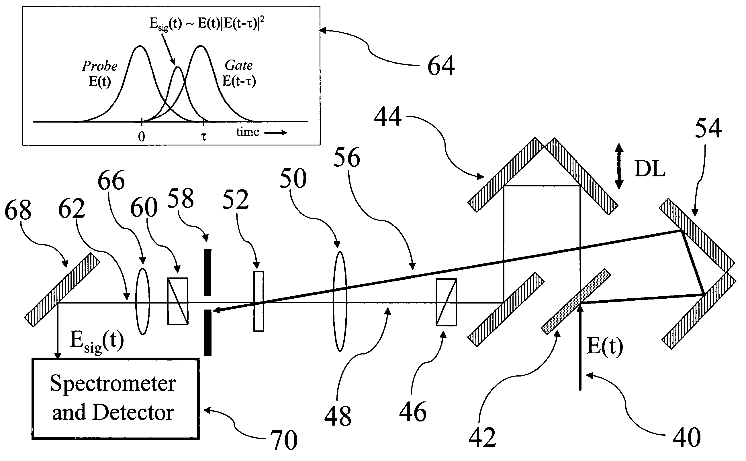
[0034]A preferred implementation may include a real-time pulse measurement device that has direct, integrated feedback that measures how well the device is retrieving pulses and tracking changes in the pulse train. This feedback may be in the form of the FROG trace error, the display of the measured and retrieved FROG trace, or another display or algorithm that can be used to provide information about the quality of the measurement.

[0035]According to one aspect, the present invention may provide a method for real-time measurement of ultrashort laser pulses comprising recording in a computer measured frequency resolved optical gating (FROG) trace data, the FROG trace data generated by processing a pulse in a FROG device. The method continues by processing the measured FROG trace to perform real time phase retrieval and to generate in real time a retrieved pulse from the measured FROG trace. The retrieved pulse is displayed. A feedback parameter is generated in real time to provide in...


PUM


Abstract

A real-time FROG system provides ultra fast pulse measurement and characterization. The system includes direct, integrated feedback that measures how well the system is retrieving pulses and tracking changes in the pulse train. This feedback is provided in real time and may be in the form of the FROG trace error, the display of the measured and retrieved FROG trace, accuracy of background subtraction or other quality measurement. The system includes preprocessing options that can be used to adjust the dynamic range of the measured signal or to perform different types of filtering. The preprocessing of the FROG trace precedes phase retrieval processing and improves the quality of pulse retrieval.

Description

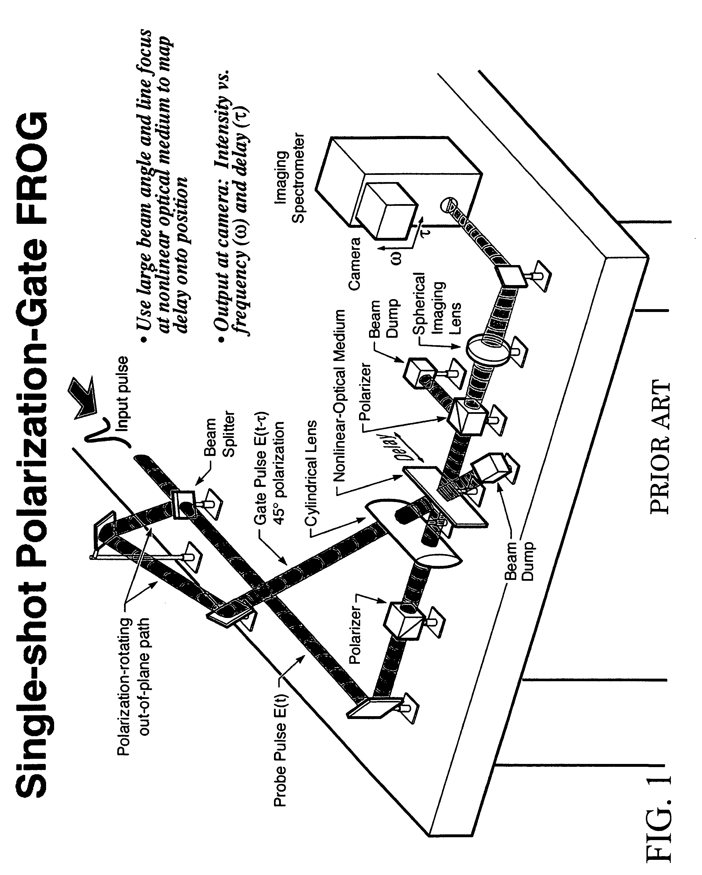
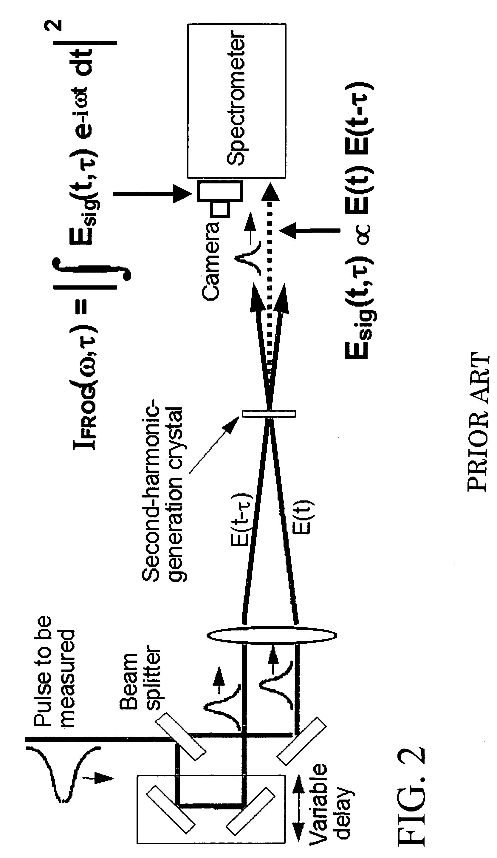
BACKGROUND OF THE INVENTION[0001]1. Field of the Invention[0002]The present invention relates to a method and apparatus for the real-time measurement of ultrashort laser pulses based on frequency-resolved optical gating (FROG).[0003]2. Background Art[0004]Ultrashort optical pulses have very short time durations, typically less than a few 10's of picoseconds. As a result, ultrashort optical pulses are spectrally broad. Because the index of refraction of materials is a function of wavelength, different wavelengths of light travel at different speeds in optical materials causing the properties of ultrashort optical pulses to change as they propagate. The shape of the pulse can influence how the pulse itself interacts with materials, further complicating the analysis of ultrashort optical pulse transmission and propagation. Ultrafast laser pulse measurement tries to obtain both the intensity profile of the pulse as well as the “phase of the pulse,” which is the actual variation of the f...

Claims


Application Information

Patent Timeline
IPC IPC(8): G01B9/02
CPCG01J11/00
Inventor KANE, DANIEL JAMES
Owner KANE DANIEL J
Learn More