
Magnetic head slider having protrusions provided on the medium-facing surface and manufacturing method therefor

a technology of magnetic head slider and medium-facing surface, which is applied in the direction of maintaining head carrier alignment, recording information storage, instruments, etc., can solve the problems of increasing abrasion, deteriorating the magnetic and low compactness of diamond-like carbon, so as to improve the corrosion of the magnetic head core provided on the slider body

Inactive Publication Date: 2006-10-31
TDK CORPARATION
View PDF20 Cites 11 Cited by
  • Summary
  • Abstract
  • Description
  • Claims
  • Application Information

AI Technical Summary

Benefits of technology

[0022]The present invention has been achieved in consideration of the above situation, and a first object of the present invention is to provide a magnetic head slider in which the abrasion resistance of protrusions provided on the medium-facing surface and rails of the slider body can be improved, and corrosion of a magnetic head core provided on the slider body can be improved.
[0023]A second object of the present invention is to provide a magnetic head slider in which the abrasion resistance of protrusions provided on rails of the slider can be improved to prevent an increase in adhesion force between the slider and a magnetic disk.
[0024]A third object of the present invention is to provide a magnetic head slider in which can further decrease adhesion between a magnetic disk and the slider body comprising protrusions provided on the medium-facing surface and rails on the magnetic disk side.

Problems solved by technology

However, the diamond-like carbon has low compactness and low degree of adhesion, and thus use as the material for the first carbon film 92 produces low corrosion resistance, causing the problem of deteriorating the magnetic core provided on the slider body.
However, in this case, the planar pressure applied to the protrusions 89 is increased to cause the problem of increasing abrasion.

Method used


Image

  • Magnetic head slider having protrusions provided on the medium-facing surface and manufacturing method therefor
  • Magnetic head slider having protrusions provided on the medium-facing surface and manufacturing method therefor
  • Magnetic head slider having protrusions provided on the medium-facing surface and manufacturing method therefor

Examples


experimental example 1

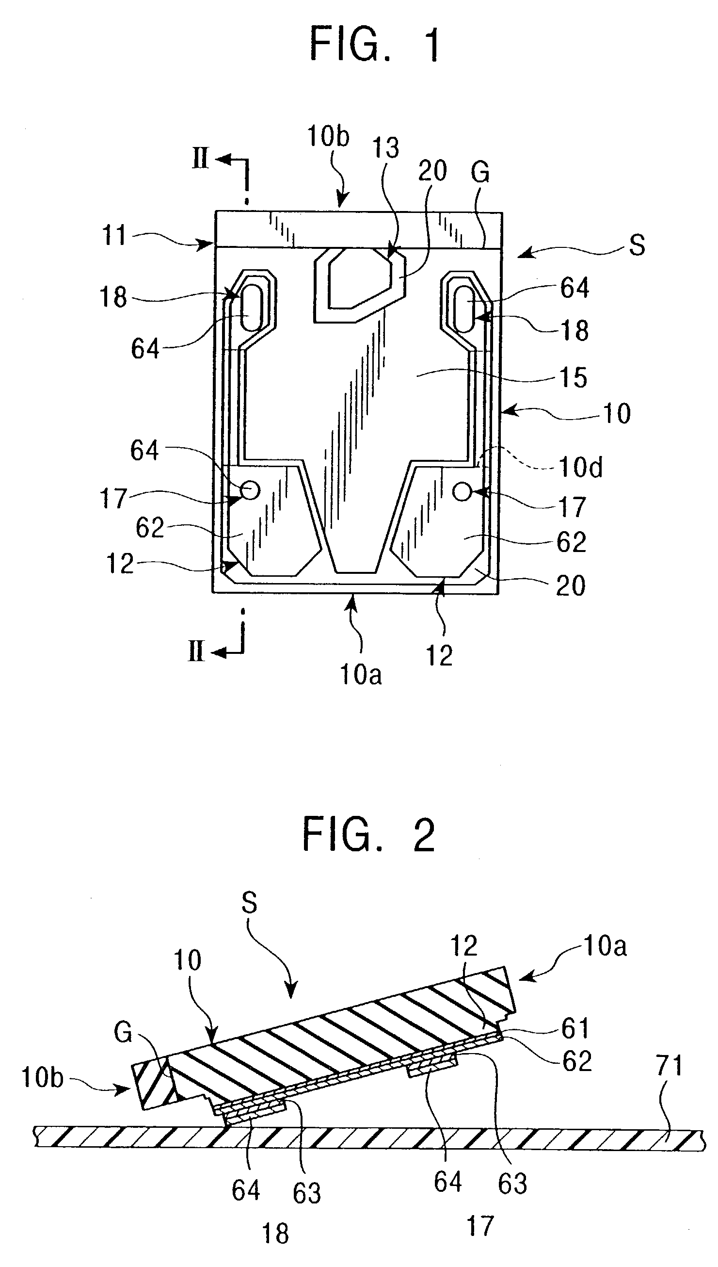
[0283]In manufacturing a magnetic head slider having the shape shown in FIGS. 1 and 2, the material used for forming the second carbon film 64 on the outermost surface of each of the first and second protrusions 17 and 18 was changed to A, B, C and D below to examine the film hardness and abrasion resistance of the protrusions. The results are shown in FIGS. 19 and 20.

[0284]In the magnetic head slider manufactured in this example, the rectangular slider body 10 had a long side length of 1.241 mm and a width of 1.0 mm, the negative pressure groove 15 had an air flow inlet side width of 0.1 mm, a maximum width 0.78 mm, and a depth (the distance from the surface of the step 20) of 2.5 μm, each of the side rails 12 had a maximum width of 0.34 mm, a minimum width of 0.08 mm, and a height (the distance from the surface of the step 20) of 0.25 μm, the Si adhesive layer 61 had a thickness of 0.5 nm, the first carbon film had a thickness of 4.5 mm, the first protrusions 17 had a diameter of ...

experimental example 2

[0293]The magnetic head slider S was manufactured by the same method as Experimental Example 1 except that the second carbon film 64 of each of the first and second protrusions 17 and 18 was made of the material B, and the first carbon film formed on each of the side rails 12 was changed in the range shown in Table 1 below. The amount of the lubricant adhered and the abrasion resistance of the protrusions were measured. In this example, perfluoropolyether was used as the lubricant.

[0294]The results are shown in Table 1. In the column of the amount of the lubricant adhered in Table 1, ◯ shows no adhesion of the lubricant, and Δ shows the occurrence of adhesion of the lubricant. In the column of the abrasion resistance in Table 1, ⊚ shows substantially no abrasion resistance of protrusions, and an abrasion amount lower than the measurement limit of the abrasion amount, ◯ shows a small abrasion amount of the protrusions of 5 nm or less, and Δ shows a large abrasion amount of the protru...

experimental example 3

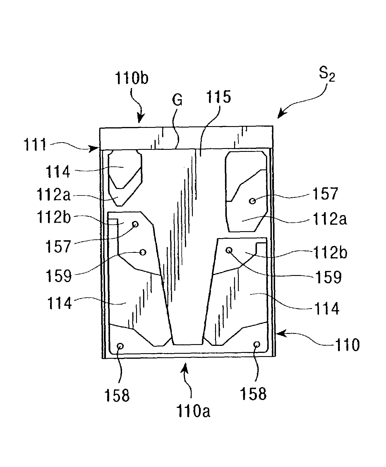
[0297]In manufacturing a magnetic head slider having the shape shown in FIGS. 7 and 8, the material used for forming the first and second protrusions 117 and 118 was changed to A, B, C and D below to examine the film hardness and abrasion resistance of the protrusions. The results are shown in FIGS. 21 to 23.

[0298]In the magnetic head slider manufactured in this example, the rectangular slider body 110 had a long side length of 1.2 mm and a width of 1.0 mm, the negative pressure groove 115 had an air flow inlet side width of 0.12 mm, a maximum width 0.36 mm, a depth of 2.5 μm, and a distance of 0.17 μm from the surface of the steps 120, each of the side rails 112 had a maximum width of 0.34 mm, and a minimum width of 0.06 mm, the first protrusions 117 had a diameter of 30 mm, the second protrusions 118 had a long diameter of 75 mm, and a short diameter of 30 mm, each of the first and second protrusions 117 and 118 had a height of 35 nm, and the distance between the second protrusion...


PUM

PropertyMeasurementUnit
thicknessaaaaaaaaaa
thicknessaaaaaaaaaa
open angleaaaaaaaaaa

Abstract

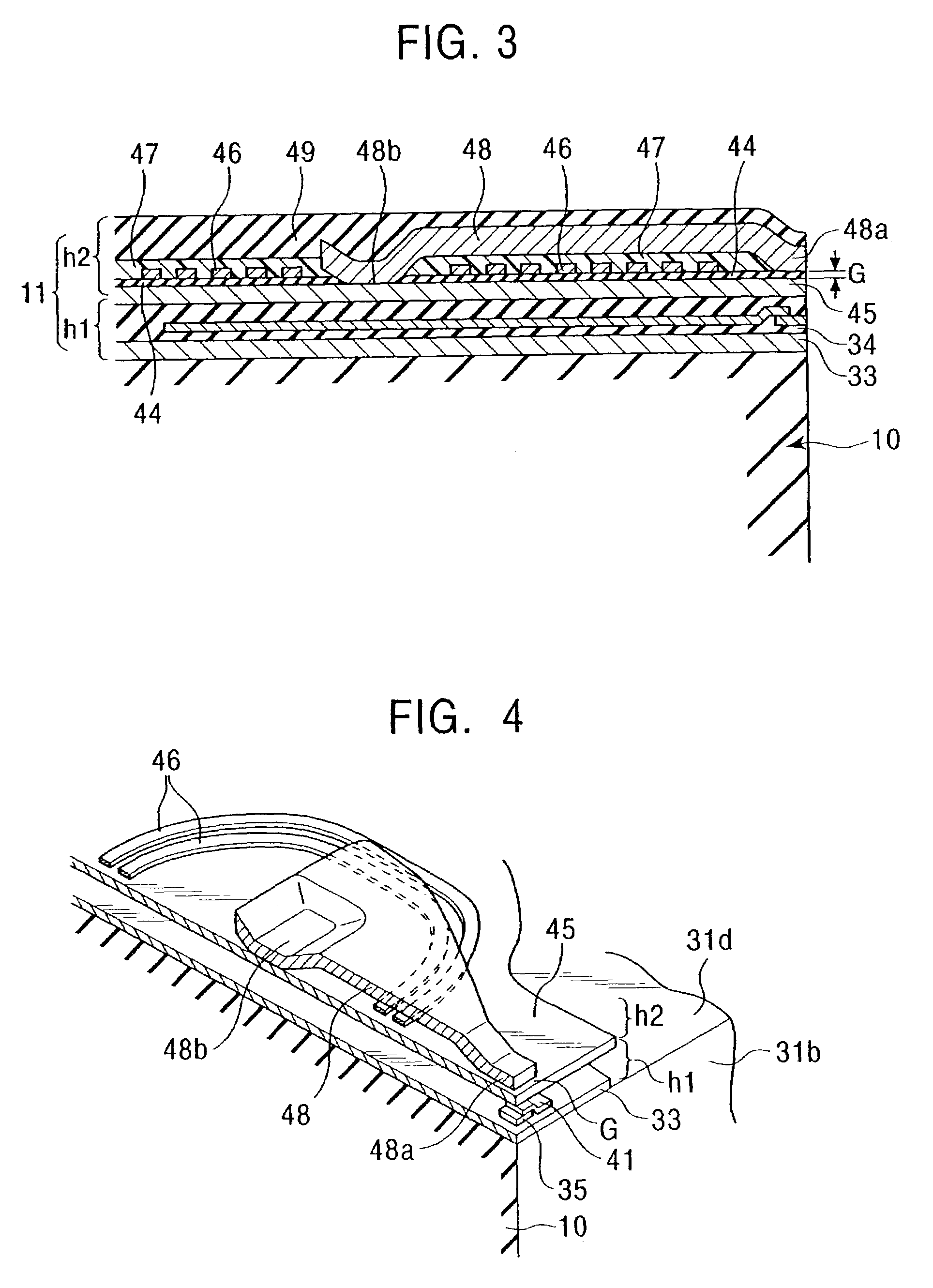
The present invention provides a magnetic head slider including rails formed on the medium-facing surface on the magnetic disk side for generating buoyant force so that the slider flies and moves above a magnetic disk to write or read magnetic information. In the magnetic head slider, a first carbon film having corrosion resistance is provided on the surfaces of the rails provided on the medium-facing surface of the slider body through an adhesive layer, protrusions formed by alternately laminating an intermediate film and a second carbon film are provided on the first carbon film, and at least the outermost second carbon film of the second carbon films, which constitute each of the protrusions, has abrasion resistance.

Description

[0001]This application is a divisional application of U.S. application Ser. No. 09 / 749,961 filed on Dec. 27, 2000, now U.S. Pat. No. 6,728,069, entitled “Magnetic Head Slider Having Protrusions Provided On The Medium-Facing Surface And Manufacturing Method Therefor”.BACKGROUND OF THE INVENTION[0002]1. Field of the Invention[0003]The present invention relates to a magnetic head slider flying above a magnetic recording medium with a small distance therebetween to record and reproduce magnetic information, and a manufacturing method therefor. Particularly, the present invention relates to a technique for improving the abrasion resistance of protrusions provided on the medium-facing surface and rails of a slider body while maintaining the manufacturing efficiency high. The present invention also relates to a technique for preventing corrosion of a magnetic head core provided on the slider body.[0004]2. Description of the Related Art[0005]As a conventional magnetic recording apparatus fo...

Claims


Application Information

Patent Timeline
Patent Type & Authority Patents(United States)
IPC IPC(8): G11B17/32G11B5/60G11B21/21
CPCG11B5/6005G11B21/21
Inventor OTSUKA, TOMOOISHIHARA, HIROHISA
Owner TDK CORPARATION
Learn More