Multi-chip facet cutting saw blade and related method

a saw blade and chip facet technology, applied in the field of saw blades, can solve the problems of cutting surface definition, blades may tend to wander laterally, provide a crooked cut, etc., and achieve the effects of improving blade life and straightness, reducing wear and/or blade life, and increasing band speed and/or feed ra

Active Publication Date: 2006-11-07
BLACK & DECKER INC
View PDF22 Cites 41 Cited by
  • Summary
  • Abstract
  • Description
  • Claims
  • Application Information

AI Technical Summary

Benefits of technology

[0017]One advantage of the currently preferred embodiments of the saw blades of the present invention is that they provide improved blade life and straightness of cut. In addition, currently preferred band saw blade embodiments of the present invention provide the ability to cut at significantly higher band speeds and / or feed rates in comparison to prior art band saw blades, and / or permit significantly improved wear and / or blade life at higher band speeds and / or feed rates in comparison to prior art band saw blades.

Problems solved by technology

One of the drawbacks associated with these and like prior art band saw blades is that the cutting surfaces are defined by the relatively wide flat upper surfaces of the teeth.
As a result, the blades may tend to wander laterally during cutting, particularly when cutting relatively large diameter workpieces, such as steel bars greater than about 15 or 20 inches in diameter or width.
Thus, the blades may provide a crooked cut, or otherwise may not provide as straight a cut, or consistently as straight a cut, as otherwise desired.
Another drawback associated with these and like prior art band saw blades is that the wider or outer teeth tend to take a greater cutting load than the inner or more narrow teeth.
In addition, at higher feed rates, the wider or outer teeth tend to take progressively greater cutting loads.
As a result, the tooth loading can be relatively unbalanced, which, in turn, can lead to premature failure, or shorter wear life than otherwise desired.
As a result, conventional band saw blades typically require a trade off between higher production rates (e.g., faster band speeds and / or feed rates) and wear or blade life.
Thus, the longer the wear or blade life, the lower the production rates, and vice versa.

Method used


Image

  • Multi-chip facet cutting saw blade and related method
  • Multi-chip facet cutting saw blade and related method
  • Multi-chip facet cutting saw blade and related method

Examples


Embodiment Construction

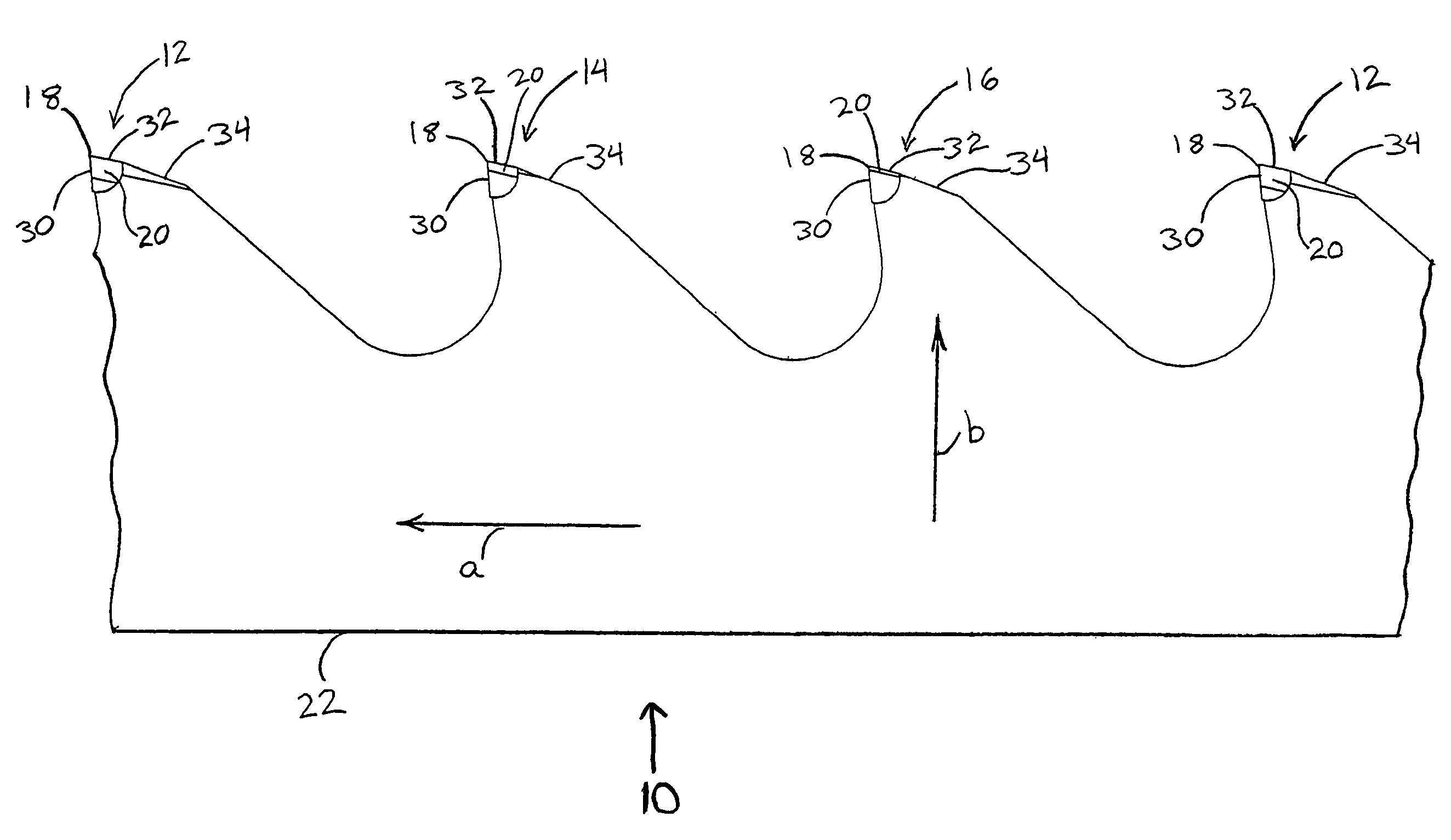
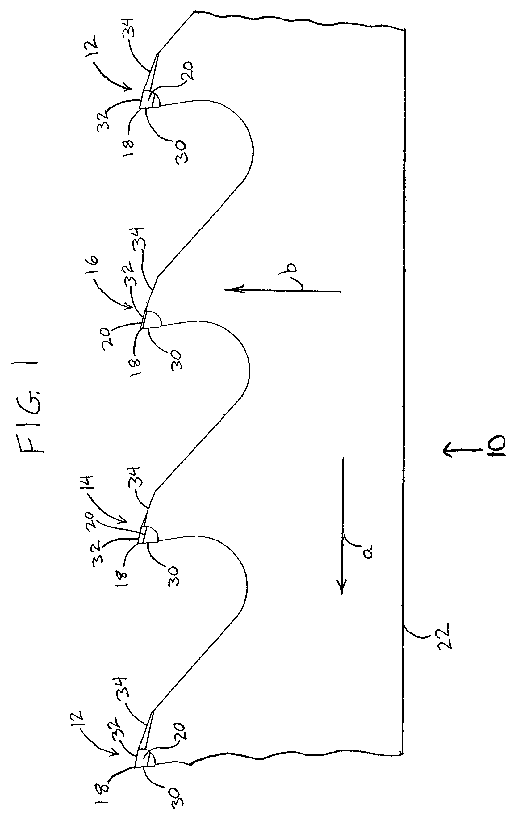
[0027]In FIG. 1, a band saw blade embodying the present invention is indicated generally by the reference numeral 10. The band saw blade 10 defines a cutting direction indicated by the arrow “a”, and a feed direction indicated by the arrow “b”. The band saw blade 10 comprises a plurality of recurrent or repetitive patterns of teeth. In the illustrated embodiment, each pattern is defined by a recurrent group of three successive teeth indicated by the reference numerals 12, 14 and 16. Each tooth defines a respective pitch or tooth spacing that can be measured between the tips of adjacent teeth, or if desired, can be measured between any of numerous other corresponding points between adjacent teeth. In the currently preferred embodiments of the present invention, the repeating tooth patterns include between about 3 and about 7 teeth. However, as may be recognized by those of ordinary skill in the pertinent art based on the teachings herein, the repeating tooth patterns may include a di...


PUM

PropertyMeasurementUnit
acute anglesaaaaaaaaaa
angleaaaaaaaaaa

Abstract

A metal cutting band saw blade has a plurality of cutting teeth defining a cutting direction, and a repeating tooth pattern of between 3 and 7 teeth. Each tooth defines a laterally-extending upper surface having a width and a height with respect to the back edge of the blade, and side surfaces extending laterally and downwardly on opposite sides of the upper surface relative to each other at acute angles relative to the upper surface. The teeth located rearwardly of the first tooth with respect to the cutting direction of the saw blade define progressively lower heights and progressively smaller acute angles of the side surfaces, and the widths of the upper surfaces of these teeth are greater than the width of the upper surface of the respective first tooth.

Description

CROSS-REFERENCE TO RELATED APPLICATION [0001]This application claims priority to U.S. Provisional Application No. 60 / 503,338 filed on Sep. 16, 2003, titled “Multi-Chip Facet Cutting Saw Blade and Related Method”, and is hereby expressly incorporated by reference as part of the present disclosure.FIELD OF THE INVENTION [0002]The present invention relates to saw blades, and more particularly, to saw blades, such as band saw blades, that include repeating patterns of cutting teeth having cutting surfaces formed by flat upper surfaces and side surfaces oriented at oblique angles relative to a central plane of the blade and / or of a respective tooth.BACKGROUND INFORMATION [0003]U.S. Pat. No. 5,477,763 to Kullman shows a band saw blade having a plurality of unset teeth provided in recurring cycles, wherein each recurring cycle includes first and second groups of teeth, with the teeth of the second group being interspersed among the teeth of the first group. The teeth in the first group pro...

Claims


Application Information

Patent Timeline
Patent Type & Authority Patents(United States)
IPC IPC(8): B27B33/02B23D61/12
CPCB23D61/121Y10T83/935Y10T83/9367Y10T83/9346Y10T83/9358
Inventor HALL, KENNETHSUKADHARE, DAYANANDA
Owner BLACK & DECKER INC
Why Eureka
Try Eureka