Engine air intake device

a technology for air intake and engine, which is applied in the direction of combustion engines, combustion-air/fuel-air treatment, charge feed systems, etc., can solve the problems of high cost of machining and inability to obtain the output increasing

Active Publication Date: 2006-11-07
NISSAN MOTOR CO LTD
View PDF7 Cites 28 Cited by
  • Summary
  • Abstract
  • Description
  • Claims
  • Application Information

AI Technical Summary

Benefits of technology

[0012]The high cost of increasing the airtightness of the valve elements and valve seats of the communication valves can be alleviated by using communication valves that comprise a valve element and valve seat and are made as a separate entity from the structural body in which the communication passages are formed (hereinafter called “passage structural body”). Such separate-entity communication valves are installed as a unit into the passage structural body after both the communication valve and the passage structural body have been fabricated. However, there has been a need for improving the airtightness between the communication valve and the passage structural body in order to prevent degradation of the resonance effect.
[0013]The present invention was conceived in view of these problems with the conventional engine air intake device having a collector divided into two volume chambers by a partition wall and a communication valve mounted in the partition wall. One object of the present invention is to provide an engine air intake device that can make the intake system more compact and improve the output performance of the engine in an effective manner by preventing the air flow resistance from increasing due to the communication valve.
[0014]Another object of the present invention is to provide a seal structure that can improve the seal performance between the two volume chambers in the engine air intake device in which the communication valve is configured as a separate entity from the structural body in which the communication passages are formed.

Problems solved by technology

Consequently, particularly when the communication valve is fully open, the air flow resistance increases and the output declines, making it impossible to obtain the output increasing effect that the valves are intended to provide.
Consequently, highly precise machining is required in order to maintain a high degree of airtightness when the communication valves are closed, and such machining is expensive.

Method used


Image

  • Engine air intake device
  • Engine air intake device
  • Engine air intake device

Examples


Embodiment Construction

[0026]Selected embodiments of the present invention will now be explained with reference to the drawings. It will be apparent to those skilled in the art from this disclosure that the following descriptions of the embodiments of the present invention are provided for illustration only and not for the purpose of limiting the invention as defined by the appended claims and their equivalents.

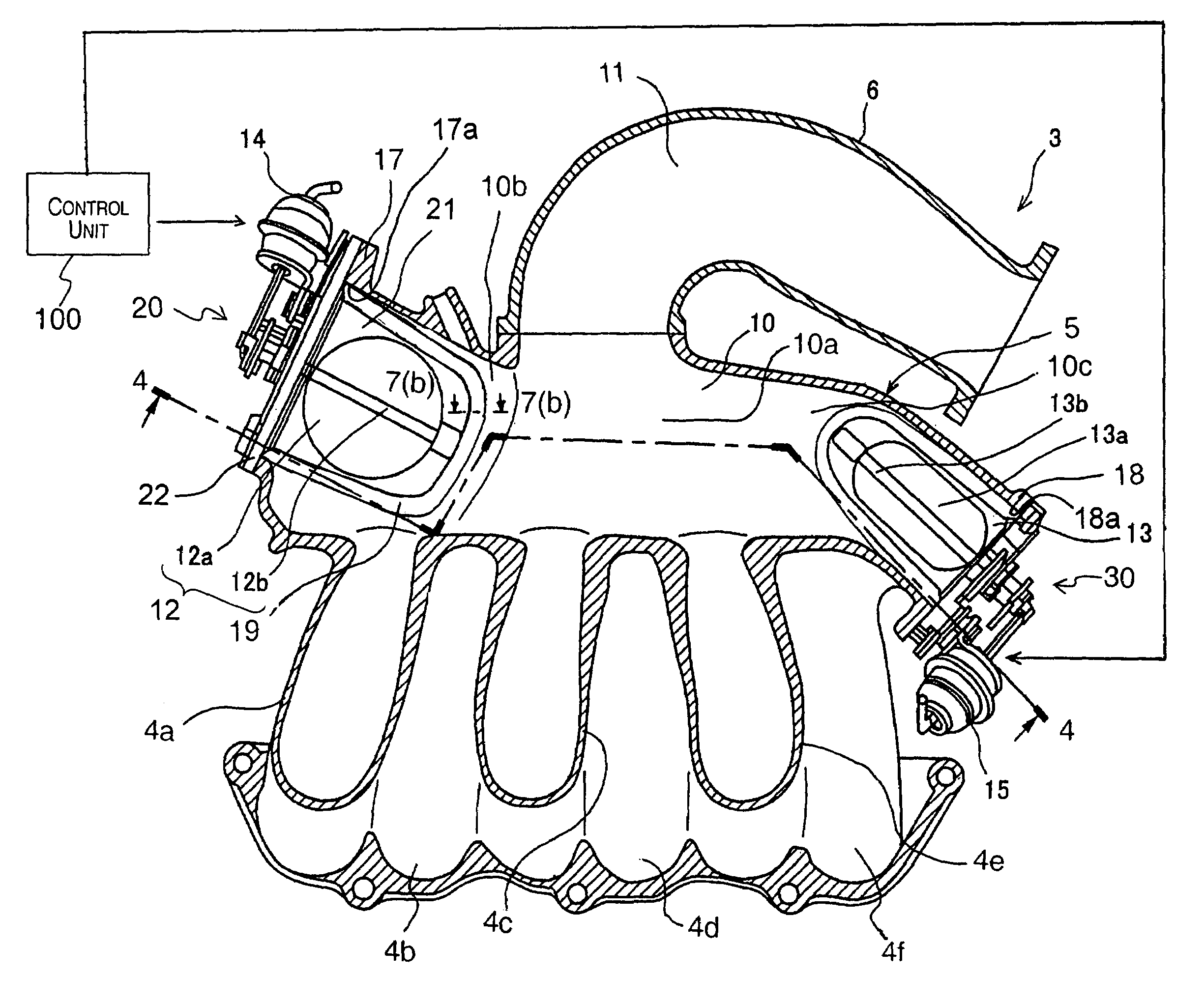
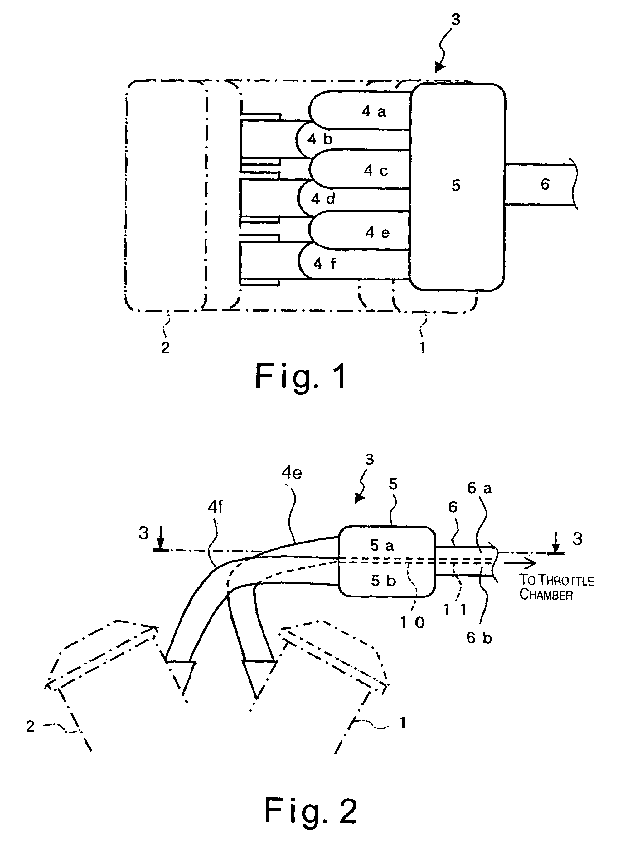
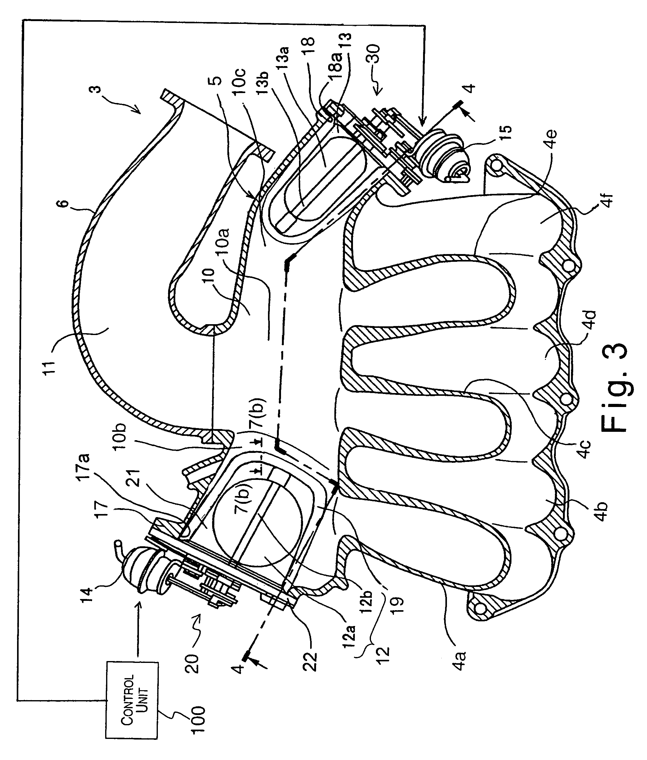
[0027]Referring initially to FIG. 1, an engine air intake device is illustrated in accordance with a first embodiment of the present invention. FIG. 1 is a schematic top plan view of an engine in which the air intake device in accordance with the first embodiment of the present invention has been employed. FIG. 2 is a schematic front elevational view of the engine. FIG. 3 is a cross sectional view of the engine air intake device of the first embodiment taken along a section line 3—3 in FIG. 2. FIG. 4 is a cross sectional view of the engine air intake device of the first embodiment taken along a sec...


PUM


Abstract

An engine air intake device comprises a collector divided by a partition wall into first and second volume chambers, first and second upstream intake pipe portions, a plurality of first and second downstream branch pipes, and a first communication valve. The first and second upstream intake pipe portions are connected to an upstream side of the first and second volume chambers, respectively. The first and second downstream branch pipes extend from the first and second volume chambers, respectively, to respective intake ports of first and second banks of first and second cylinders, respectively. The first communication valve is mounted to the partition wall in a position that does not interfere with a path of a main flow of intake air inside the collector and configured and arranged to allow communication between the first volume chamber and the second volume chamber when the first communication valve is open.

Description

CROSS-REFERENCE TO RELATED APPLICATIONS[0001]This application claims priority to Japanese Patent Application Nos. 2004-214098 and 2004-215730. The entire disclosures of Japanese Patent Application Nos. 2004-214098 and 2004-215730 are hereby incorporated herein by reference.BACKGROUND OF THE INVENTION[0002]1. Field of the Invention[0003]The present invention generally relates to an engine air intake device configured to execute variable resonance supercharging with respect to the intake air delivered to an internal combustion engine. More specifically, the present invention relates to an engine air intake device provided with two independent volume chambers (collector sections), each of which corresponds to one of two banks for two cylinder groups, two upstream intake pipe portions that connect to the upstream sides of each of the volume chambers, and at least one communication valve configured to allow communication between the two volume chambers. Moreover, the present invention re...

Claims


Application Information

Patent Timeline
Patent Type & Authority Patents(United States)
IPC IPC(8): F02M35/10
CPCF02B27/02F02B27/0252F02D9/101F02D9/1045F02D2009/0277F02D2009/0281Y02T10/146F02B27/021F02B27/0273Y02T10/12
Inventor SASAKI, JUNYAKOTOUGE, ATSUROU
Owner NISSAN MOTOR CO LTD
Why Eureka
Try Eureka