Microfluidic two-way isolation valve

a two-way isolation valve, microfluidic technology, applied in the field of valves, can solve problems such as material pitting corrosion, and achieve the effects of low power consumption, fast operation speed, and small manufacturing

Active Publication Date: 2006-11-07
NORGREN KLOEHN LLC
View PDF8 Cites 13 Cited by
  • Summary
  • Abstract
  • Description
  • Claims
  • Application Information

AI Technical Summary

Benefits of technology

[0015]The fluid internal to the valve that is not easily flushed out during a purge cycle defines a dead volume that is approximately equal to zero. This avoids the problem of carryover. The valve is designed for zero leakage past the diaphragm assembly. Thus, the solenoid-operated valve may preferably comprise an isolation valve.
[0038]The valve may further comprise a mag disc configured to fit around the mag pin at an end thereof. The mag disc configuration is chosen for optimum strength of the magnetic field and optimum performance of the valve.
[0043]A method of making a solenoid-operated valve is also provided. The method comprises the steps of providing a coil housing defining an axis, disposing a solenoid actuated plunger rod within the coil housing allowing for axial movement of the plunger rod, providing an air gap adjacent to the solenoid actuated plunger rod, and setting the dispense volume of the pump by precisely setting the size of the air gap. The method further comprises providing a spring having a spring force configured axially with the plunger rod to assist axial movement of the plunger rod.
[0045]It is an object of the present invention to provide a solenoid-operated valve design and method particularly for small manufacture. It is another object of the present invention to provide a valve design for small dispense volumes, small internal volume, and fast operating speed. It is yet a further object of the present invention to provide a valve design particularly suited for a compact, high-density valve manifold. It is yet a further object of the present invention to provide a solenoid valve design for low power consumption. Another object of the present invention is to provide a solenoid-operated valve that is easy to manufacture, simple to use, and cost effective.

Problems solved by technology

For instance, blood is a natural oxidizing agent and will cause some material to undergo pitting corrosion.

Method used


Image

  • Microfluidic two-way isolation valve
  • Microfluidic two-way isolation valve
  • Microfluidic two-way isolation valve

Examples


Embodiment Construction

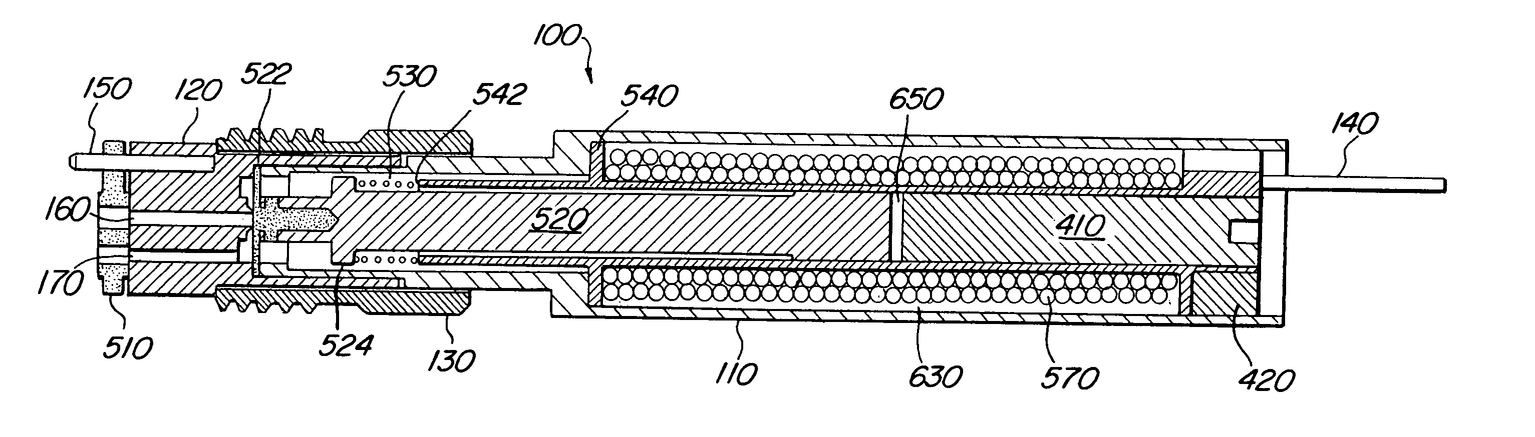
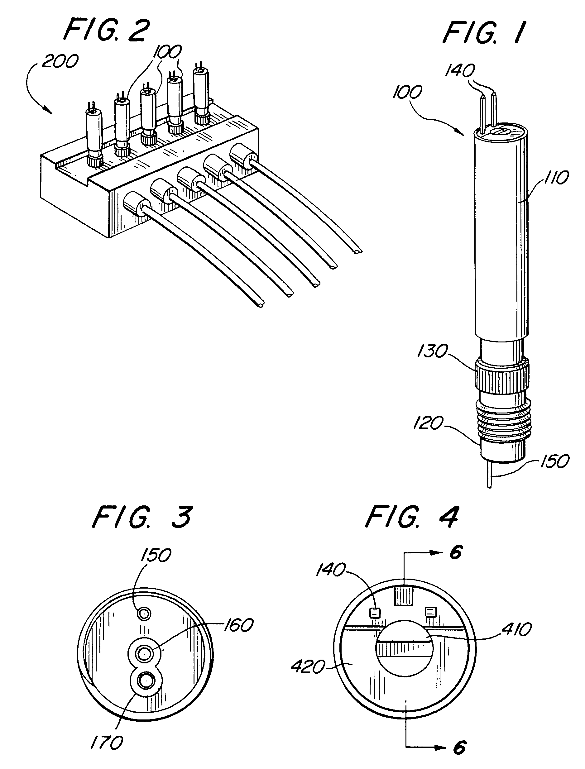
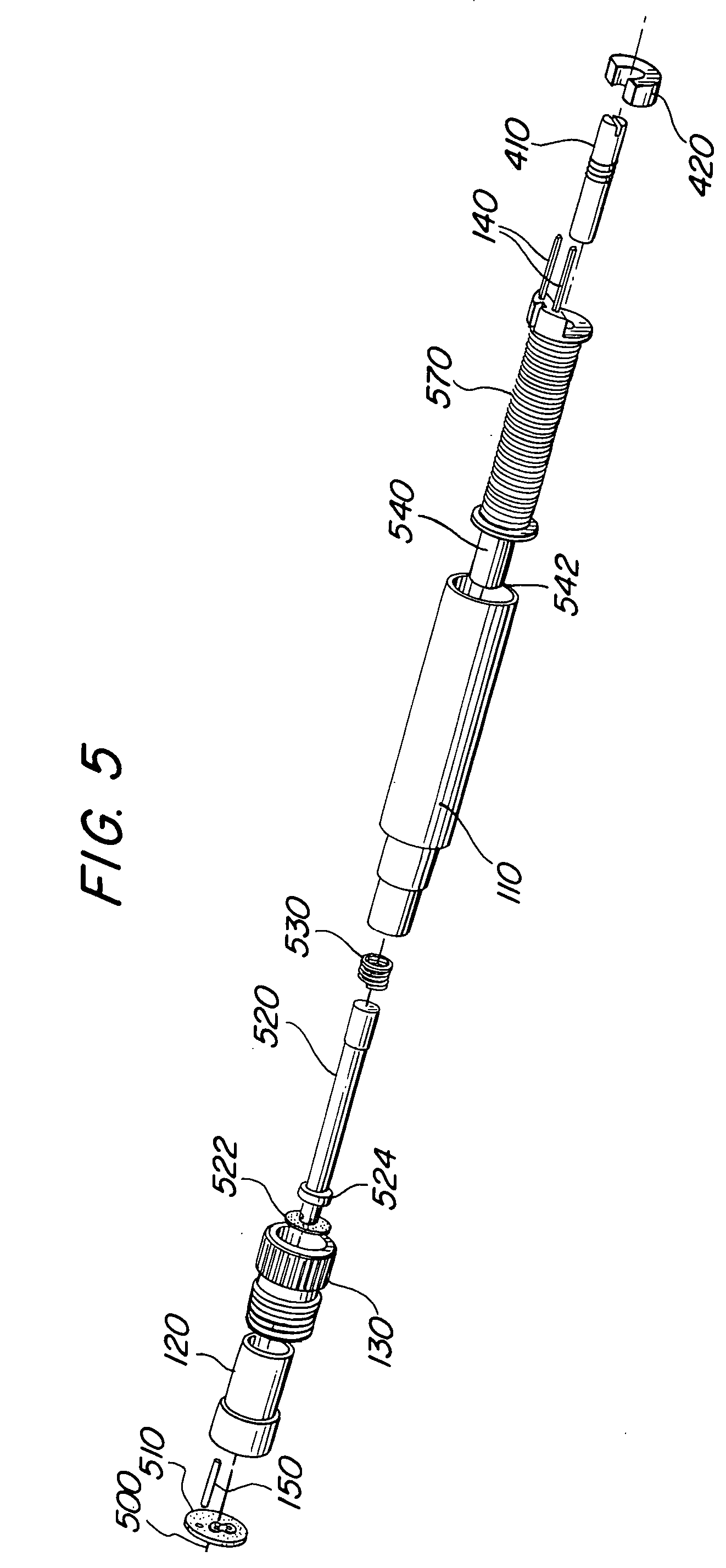
[0059]Referring initially to FIG. 1, a first preferred embodiment of a solenoid-operated valve 100 according to the present invention is shown. The valve 100 comprises external components including a coil housing 110 and an end cap 120. A manifold screw 130 partially surrounds portions of the coil housing 110 and the end cap 120. A rear end of the solenoid valve 100 includes electrical leads 140 that provide power to energize a solenoid coil 570 (FIG. 5). A locating pin 150 properly aligns valve inlet and outlet ports 160, 170 (FIG. 3), respectively, to a valve manifold 200.

[0060]FIG. 2 illustrates an isometric view of the exemplary valve manifold 200. The valve 100 is compact in design and ideal for the high-density valve manifold 200. The valve 100 require minimum space, approximately less than two (2) cubic inches, and has a small diameter approximately 0.25 inches mounting in a 0.28 inch cavity, for example. This allows many valves 100 to be used in close proximity resulting in ...


PUM


Abstract

A solenoid-operated valve design and method particularly for suited for micro-fluidic applications are disclosed. The solenoid valve contains various structure and features that provide for small dispense volumes, small internal volume, and fast operating speed. Also disclosed is a valve design and method particularly suited for a compact, high-density valve manifold. In a particular embodiment disclosed, the valve uses a diaphragm assembly that ensures zero or little leakage. The solenoid-operated valve further has features allowing for low power consumption.

Description

PRIORITY CLAIM[0001]Priority is claimed from U.S. Provisional Patent Application Ser. No. 60 / 496,440, filed on Aug. 18, 2003 and entitled “Micro-Mini Two-Way Isolation Valve” pursuant to 35 USC §119, the entire contents of this provisional patent application are hereby expressly incorporated by reference.BACKGROUND OF THE INVENTION[0002]1. Field of the Invention[0003]The present invention pertains generally to valves for physical transport and isolation of liquids and gases. More particularly, the present invention pertains to solenoid-operated isolation valves that are designed for low power and quick dispensing applications. The present invention, in a preferred embodiment, is particularly but not exclusively, useful as a solenoid-operated valve for micro-fluidic platforms with high-density manifolds, and method of manufacturing the same.[0004]2. Description of the Prior Art[0005]Solenoid-operated valves for isolation and transport of fluids are well known. An attractive character...

Claims


Application Information

Patent Timeline
Patent Type & Authority Patents(United States)
IPC IPC(8): F16K31/02F16K27/00F16K31/06
CPCF16K27/003F16K31/0658F16K31/0675
Inventor KISH, JR., WALTER J.
Owner NORGREN KLOEHN LLC
Why Eureka
Try Eureka