Self-centering braze assembly

a self-centering, braze technology, applied in the direction of non-electric welding apparatus, casting plants, wire networks, etc., to achieve the effect of increasing surface area and inhibiting braze material

Active Publication Date: 2006-11-07
BOSTON SCI NEUROMODULATION CORP
View PDF62 Cites 73 Cited by
  • Summary
  • Abstract
  • Description
  • Claims
  • Application Information

AI Technical Summary

Benefits of technology

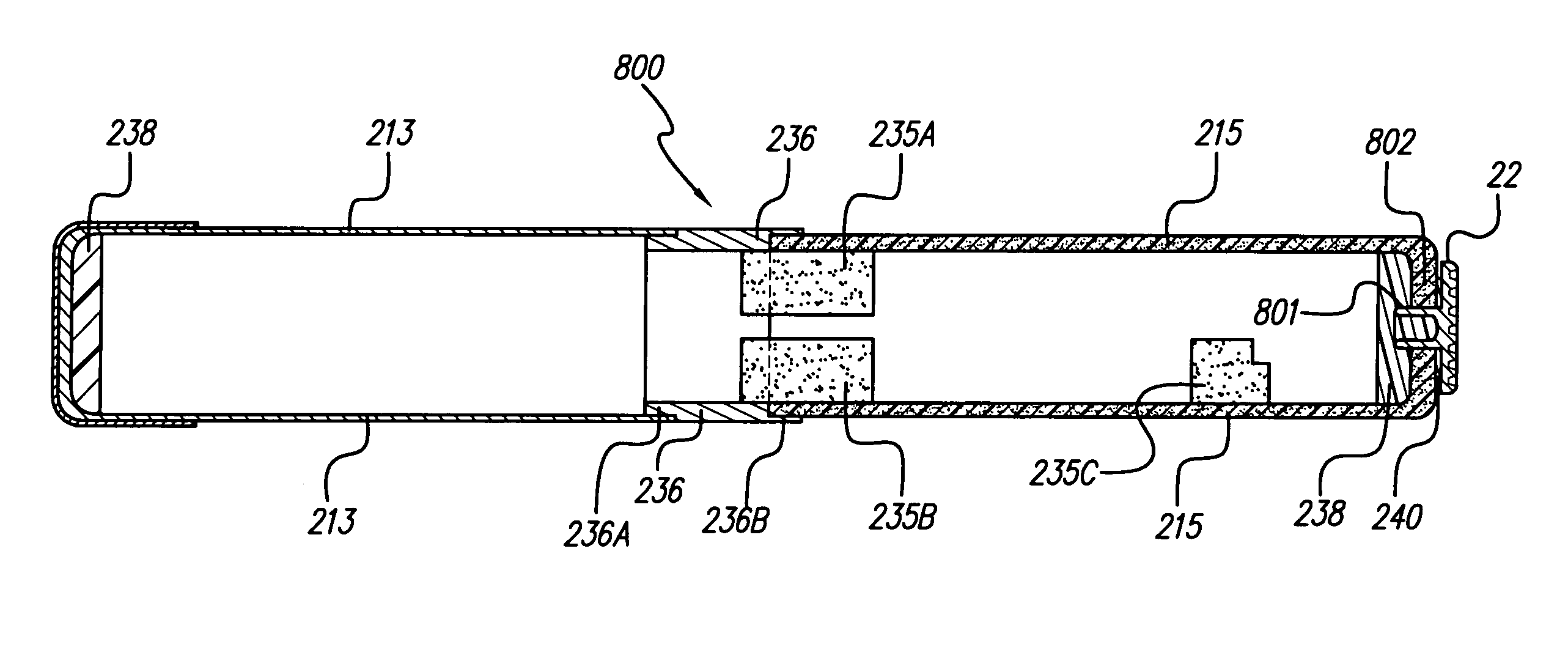
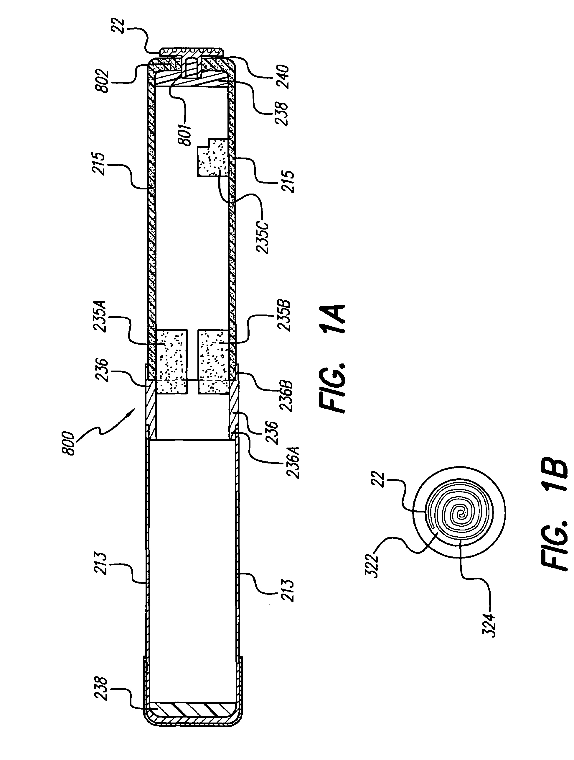
[0012]The present invention addresses the above and other needs by providing a self-centering braze assembly for hermetically sealing the metal and ceramic materials of various products, e.g., a Bion® or other microstimulator. The present invention also describes the method of assembling and brazing the materials used to create the hermetic seal of a self-centering braze assembly. The self-centering braze assembly includes increased surface area at the braze joint. This increased surface area permits the use of an adequate amount of braze material that is necessary to create a strong braze joint. At the same time, the increased surface area inhibits braze material from exuding from the braze joint. Further, the self-centering braze assembly includes a flange on a metal ring that encompasses the external, or outer-circumferential, surface of the ceramic case at the braze joint. This flange acts as a dam that inhibits braze material from exuding from the braze joint. Further, the present invention includes a ceramic case that need not be machined at the braze joint and is therefore stronger at the braze joint.

Problems solved by technology

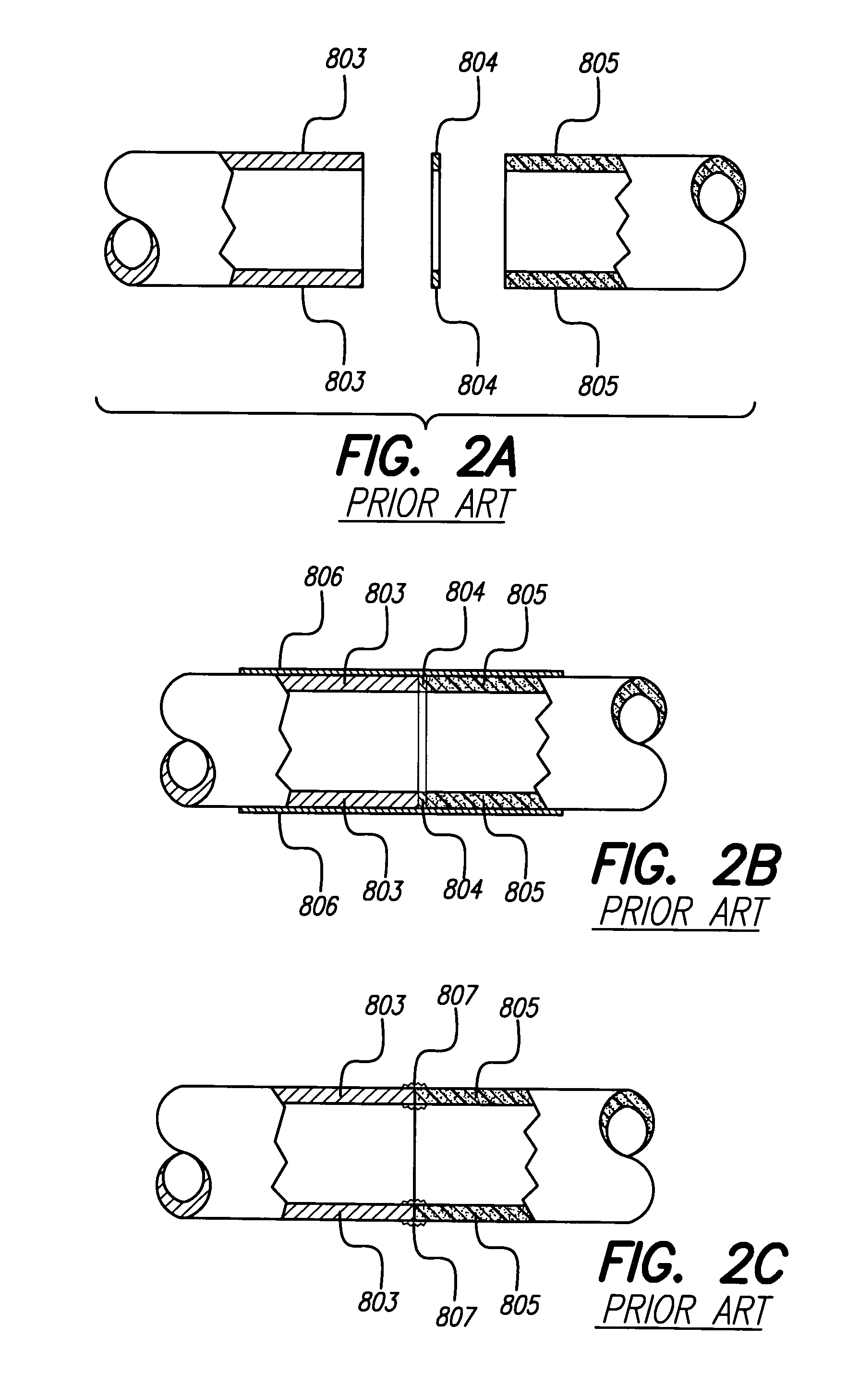
The '513 patent and the '394 and '677 publications fail to teach, inter alia, a braze assembly employing both an external flange that communicates with the outer diameter of a ceramic case and also a flange and step or other joint with adequate or increased surface area.

Method used


Image

  • Self-centering braze assembly
  • Self-centering braze assembly
  • Self-centering braze assembly

Examples


Embodiment Construction

[0050]The following description is of the best mode presently contemplated for carrying out the invention. This description is not to be taken in a limiting sense, but is made merely for the purpose of describing the general principles of the invention. The scope of the invention should be determined with reference to the claims.

[0051]The present invention may be used with numerous devices. Such devices may include implantable medical devices, such as microstimulators. However, as will be understood by those of skill in the art, the present invention may be used with other types of devices. The exemplary medical device that will be used herein to describe the systems and methods of the present invention is a small, implantable stimulator, and more particularly a microstimulator known as a Bion® microstimulator.

[0052]The Bion® microstimulator has a substantially cylindrical shape (other shapes are possible) and at least portions of it are hermetically sealed using the methods and str...


PUM

PropertyMeasurementUnit
thickaaaaaaaaaa
thickaaaaaaaaaa
thicknessaaaaaaaaaa

Abstract

Braze and electrode wire assemblies, e.g., used with an implantable microstimulator, include a wire welded in the through-hole of an electrode, which electrode is brazed to a ceramic case that is brazed to a metal ring that is welded to a metal can. The braze joints are step or similar joints that self-center the case, provide lateral support during braze assembly, and provide increased surface area that prevents braze material from exuding from the joints. The end of the ceramic case that is brazed to the metal ring need not be specially machined. The shell has a reference electrode on one end and an active electrode on the other, and is externally coated on selected areas with conductive and non-conductive materials.

Description

[0001]The present application claims the benefit of U.S. Provisional Patent Application Ser. No. 60 / 392,475, filed Jun. 28, 2002, which application is incorporated herein by reference in its entirety.FIELD OF THE INVENTION[0002]The present invention relates to braze assemblies and more particularly to self-centering braze assemblies of ceramic and metallic materials for applications such as medical devices, electrical connectors, electronics packages, and structural components.BACKGROUND OF THE INVENTION[0003]Many products made of different materials with different properties are manufactured by sealing the different materials together. A seal between two different materials can be produced by welding, gluing, brazing, or similar processes. Brazing is the process of soldering two materials with different properties, such as ceramic and metal, together using a hard solder with a relatively high melting point. One can create a very strong and lasting seal between two different materia...

Claims


Application Information

Patent Timeline
Patent Type & Authority Patents(United States)
IPC IPC(8): B32B3/06B23K1/14B32B1/04B32B1/08B32B15/00B32B15/04B32B3/08A61N1/36A61N1/372A61N1/375A61N1/378H01Q1/24H01Q7/08H02J7/00H02J17/00
CPCA61N1/37205A61N1/37229A61N1/3727A61N1/37276A61N1/375A61N1/3787H02J7/025H04L27/02H04L27/10A61N1/3605A61N1/37217A61N1/37223A61N1/36007Y10T428/12264A61N1/37235H02J7/345H04B5/0037H04B5/0081H01L2224/48465H01L2224/49175H01L2924/19105H01L2924/19107H01L2224/45144Y10T29/49073Y10T428/12375Y10T29/49968H01L2924/1461Y10T428/12806Y10T29/49155Y10T29/49169Y10T29/49128Y10T29/49945Y10T428/12271Y10T428/12396Y10T29/4913Y10T428/12347Y10T428/12535Y10T29/49826Y10T29/4902Y10T29/49071H01L2924/00H01L2224/45147H01L2924/3011H01L2924/30111H01L2924/00011A61N1/37512H02J50/10H02J2310/23H01L2924/01005H01L2924/01033
Inventor DAULTON, JAY
Owner BOSTON SCI NEUROMODULATION CORP
Why Eureka
Try Eureka