Electronic endoscope apparatus which superimposes signals on power supply

a technology of power supply and endoscope, which is applied in the field of electronic endoscope apparatus, can solve problems such as bad connections or pin breakage of some connection pins, and achieve the effect of restoring supply voltage lost and stable dc power supply

Inactive Publication Date: 2006-11-07
FUJI PHOTO OPTICAL CO LTD
View PDF6 Cites 57 Cited by
  • Summary
  • Abstract
  • Description
  • Claims
  • Application Information

AI Technical Summary

Benefits of technology

[0014]In the electronic endoscope (processor unit if the processor-side reference pulses are used), various timing signals including a clock signal, horizontal synchronizing signal, and vertical synchronizing signal are formed by PLL method in synchronization with the approximately ten reference pulses and the video signal is processed based on these signals. In the processor unit, the video signal supplied through the coaxial cable is separated by a separating circuit and video processing is performed on it to allow images of the object under observation to be displayed on a monitor in good condition.
[0015]Furthermore, a power receiving circuit may be installed in the electronic endoscope to full-wave rectify DC power superimposed with the video signal, using a full-wave rectifier circuit. Then, the DC power supplied from the processor unit and superimposed with the video signal is full-wave rectified by the full-wave rectifier circuit. This makes it possible, for example, to restore the supply voltage lost when superimposed with the video signal, allowing stable DC power supply.

Problems solved by technology

Consequently, the cable connector has a multi-pin architecture, which may cause bad connections or breakage of some connection pins in addition to being expensive.

Method used


Image

  • Electronic endoscope apparatus which superimposes signals on power supply
  • Electronic endoscope apparatus which superimposes signals on power supply
  • Electronic endoscope apparatus which superimposes signals on power supply

Examples


first embodiment

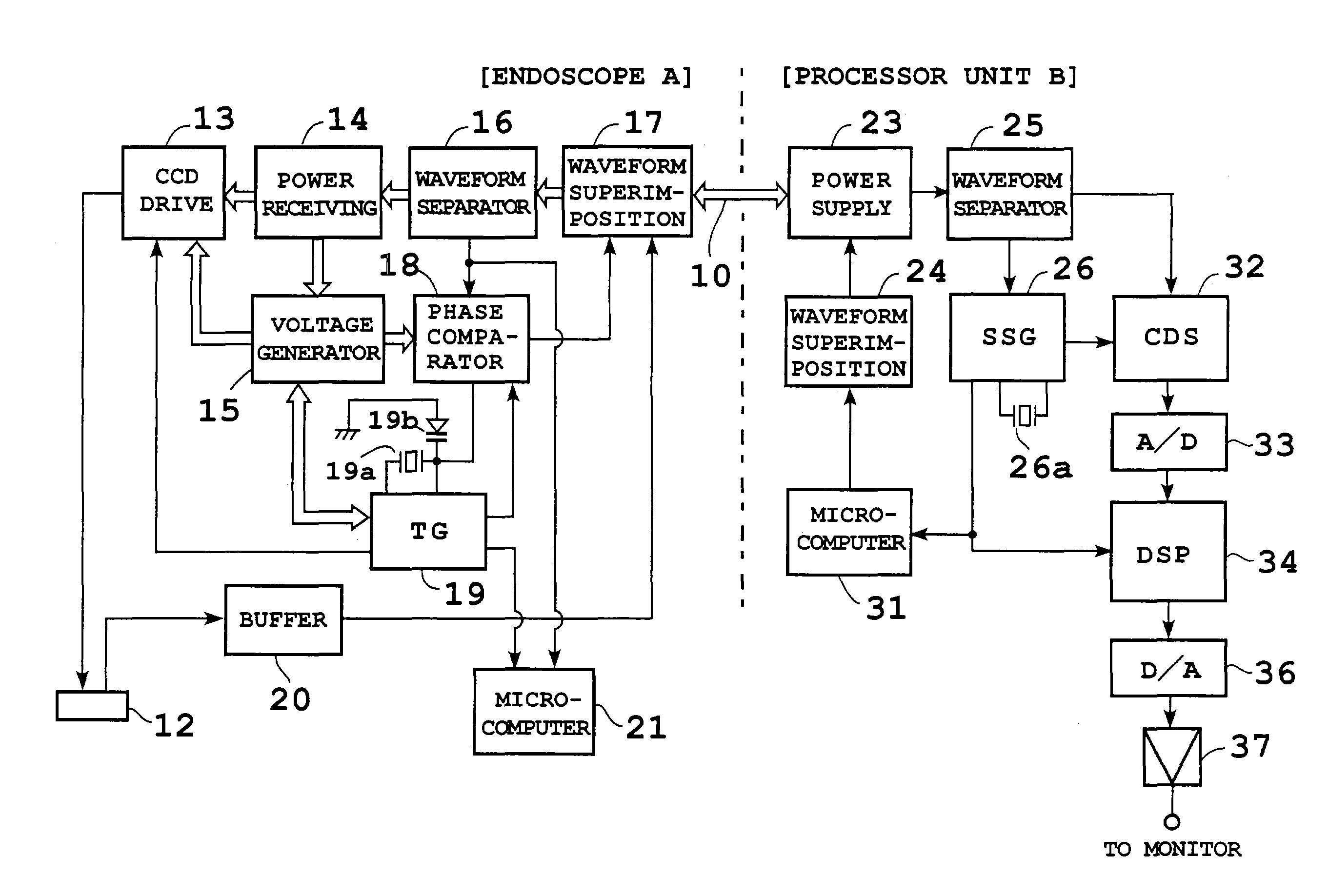
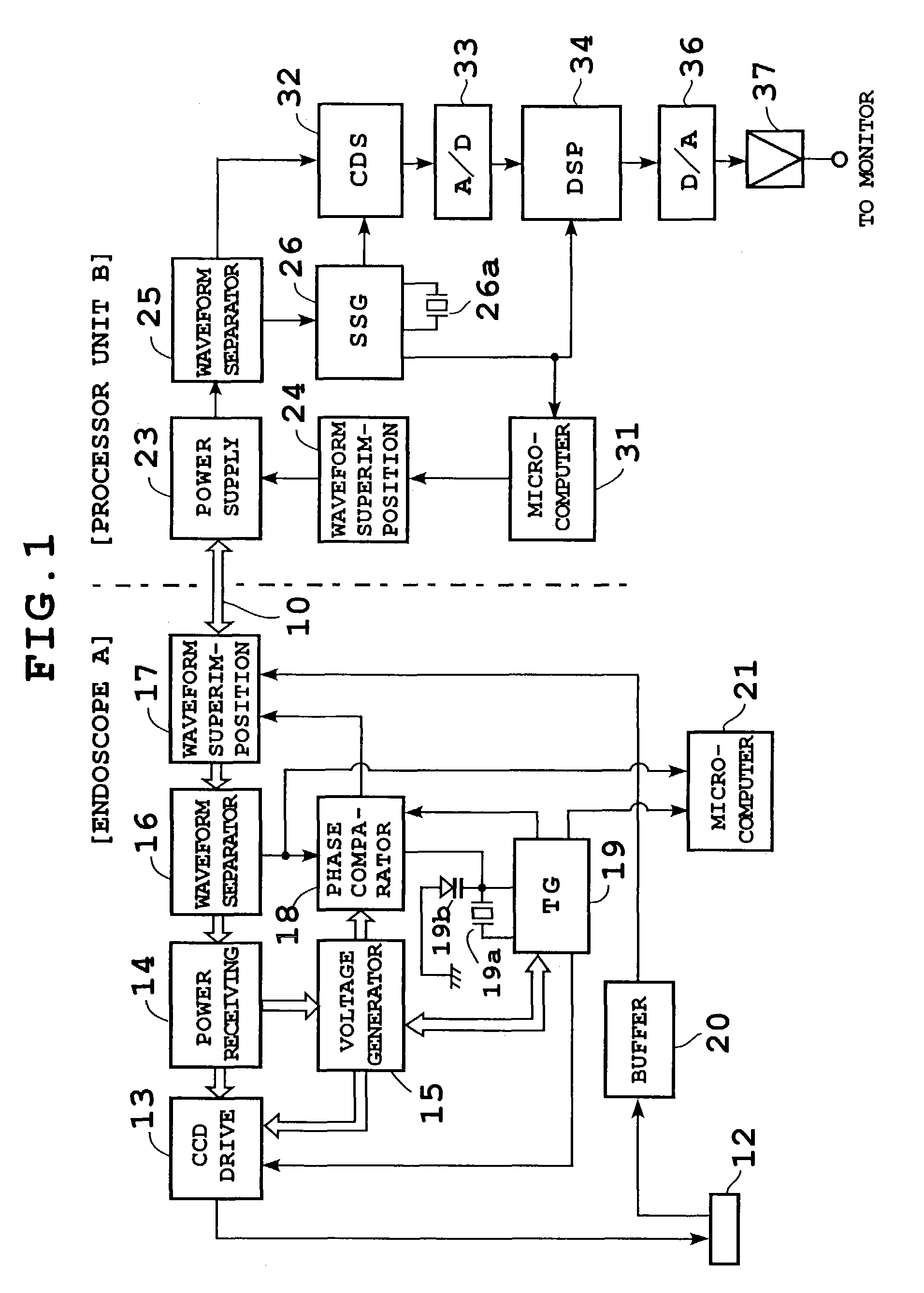
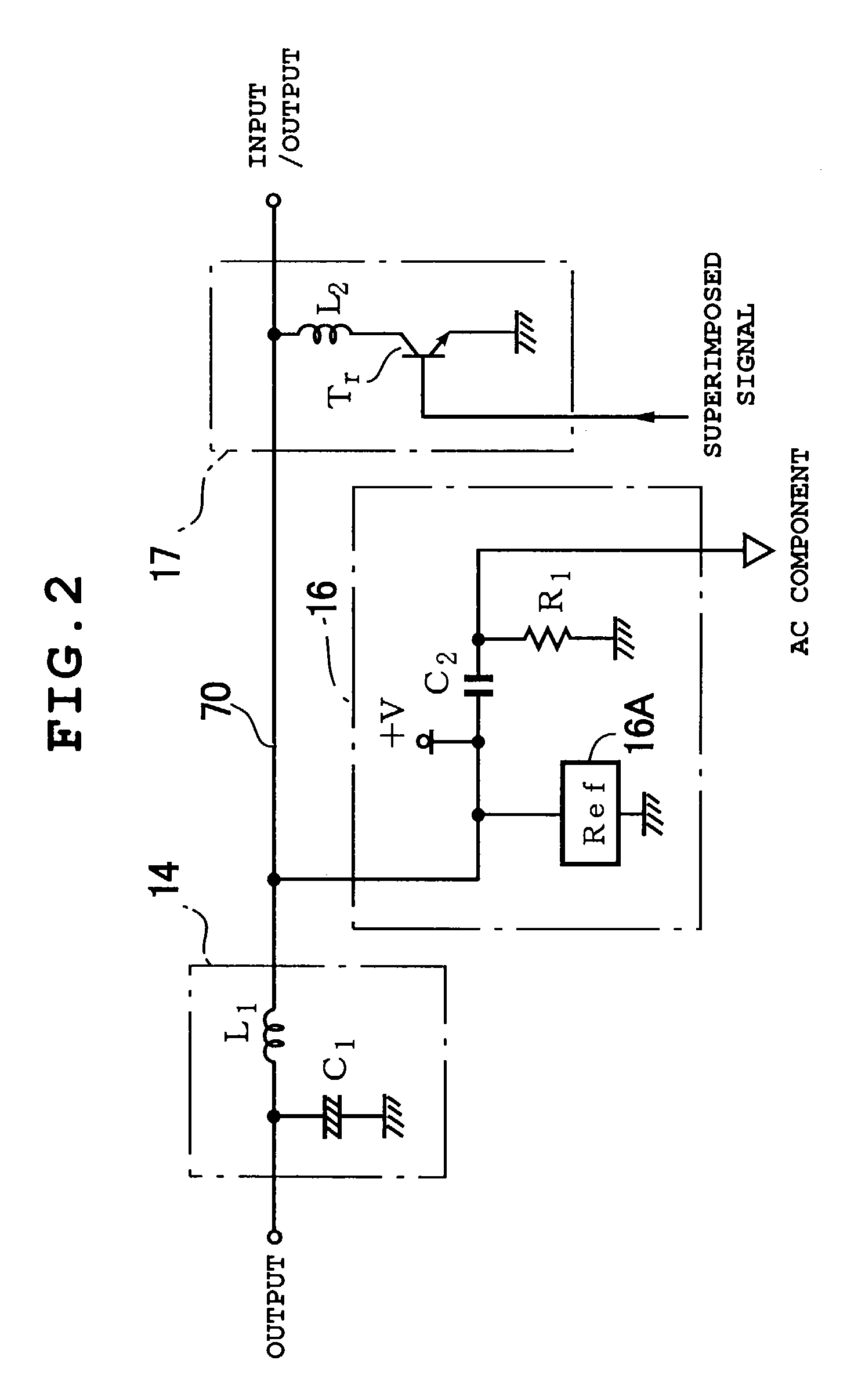
[0039]FIGS. 1 and 2 show configuration of an electronic endoscope apparatus according to a first embodiment. In FIG. 1, a scope (electronic endoscope) A is connected to a processor unit B by a single coaxial cable 10 which is a common power / signal line. The tip of the scope A is equipped with, for example, a 280,000-pixel CCD 12 and supplied with an illuminating beam (not shown) from a light source unit via a light guide.

[0040]The scope A comprises a CCD drive circuit 13 which drives the CCD 12, power receiving circuit 14 which feeds DC (direct current) power, switching regulator, etc. Also, it is equipped with a voltage generating circuit 15 which produces a plurality of supply voltages using power transmitted from the power receiving circuit 14, waveform separating circuit 16 which separates processor-side reference pulses (described later), control signals, etc. superimposed on the power transmitted through the coaxial cable 10, and waveform superimposing circuit 17 which superim...

second embodiment

[0055]FIG. 6 shows configuration of an electronic endoscope apparatus according to a second embodiment. According to this embodiment, reference pulses are sent from the scope A to the processor unit B. For that, the scope A eliminates the phase comparator circuit 18 shown in FIG. 1, and instead has a timing generator (TG) 51 equipped with a 28.6363-MHz crystal oscillator 51a while the processor unit B has a phase comparator circuit 52 and a synchronizing signal generator (SSG) 53 equipped with a 28.6363-MHz crystal oscillator 53a and a variable-capacitance diode 53b.

[0056]In the second embodiment, again DC power is supplied from the power supply circuit 23 of the processor unit B to the scope A via the coaxial cable 10. In the scope A, various circuits operate on DC power with a predetermined voltage outputted from the voltage generating circuit 15. The waveform superimposing circuit 17 in the scope A superimposes the scope-side reference pulses and the video signal obtained by the...

third embodiment

[0060]FIG. 7 shows configuration of an electronic endoscope apparatus according to a third embodiment. According to this embodiment, the tip of the scope A is equipped with, for example, a 270,000-pixel CCD 112. The scope A comprises a CCD drive circuit 113; power receiving circuit 114; voltage generating circuit 115; waveform separating circuit 116 which separates processor-side reference pulses, control signals, etc. superimposed on the power transmitted through the coaxial cable 10; waveform superimposing circuit 117 which superimposes a waveform of a video signal on transmitted power and superimposes scope-side reference pulses on a blanking period of the first horizontal line signal in the first field of the video signal; phase comparator circuit 118 which compares the phase of an oscillation signal with the phase of processor-side reference pulses (described later); and timing generator 119 which generates a clock signal (e.g., with a frequency of 19.0632 MHz) at the pixel lev...


PUM


Abstract

An electronic endoscope apparatus has a single coaxial cable which combines a power line and signal line installed between a scope and a processor unit. A waveform superimposing circuit of the scope superimposes a video signal on power transmitted through the coaxial cable and superimposes scope-side reference pulses on a blanking period of the first horizontal line signal in the first field of the video signal. On the other hand, the processor unit superimposes processor-side reference pulses on a blanking period of the first horizontal line in the second field of the video signal. Then, the scope and the processor unit perform video processing based on timing signals synchronized with the reference pulses. Alternatively, an electromagnetic coupler may be installed instead of the coaxial cable and the video signal and reference pulses may be superimposed on AC power supplied electromagnetically.

Description

BACKGROUND OF THE INVENTION[0001]This application claims the priority of Japanese Patent Applications Nos. 2002-206534 and 2002-206535 filed on Jul. 16, 2002 and No. 2002-250406 filed on Aug. 29, 2002 which are incorporated herein by reference.[0002]1. Field of the Invention[0003]The present invention relates to an electronic endoscope apparatus. More particularly, it relates to a configuration of connection wires and signal transmission for supplying power and video signals between an electronic endoscope which is a scope and a processor unit which is connected with the electronic endoscope.[0004]2. Description of the Related Art[0005]In an electronic endoscope apparatus, an electronic endoscope equipped, for example, with a CCD (Charge Coupled Device) which is a solid-state image sensor is connected to a processor unit via a cable and connector. Through these cable and connector, power is supplied and various control signals are transmitted from the processor unit to the scope whi...

Claims


Application Information

Patent Timeline
Patent Type & Authority Patents(United States)
IPC IPC(8): A62B1/04H04N7/18H04N9/47A61B1/04H04N5/225H04N5/228
CPCH04N5/23241H04N5/335H04N7/183H04N2005/2255H04N23/555H04N23/65H04N25/00
Inventor ABE, KAZUNORI
Owner FUJI PHOTO OPTICAL CO LTD
Why Eureka
Try Eureka