Electronic switching circuit employing capacitor filtering output and with front stage and back stage arranged isolatedly

An electronic switch and capacitor filtering technology, applied in electronic switches, electrical components, pulse technology, etc., can solve problems such as electric shock accidents and poor switch sensitivity, achieve low cost, reduce ripple output, and avoid malfunctions Effect

Pending Publication Date: 2016-11-09
成都立威讯科技有限公司
View PDF0 Cites 1 Cited by
  • Summary
  • Abstract
  • Description
  • Claims
  • Application Information

AI Technical Summary

Problems solved by technology

[0004] In the prior art, when designing an electronic switch circuit, the ground terminals of the input circuit and the output circuit are often shared, resulting in mutual influence between the front and rear stages, poor switch sensitivity, and even electric shock accidents in severe cases.

Method used


Image

  • Electronic switching circuit employing capacitor filtering output and with front stage and back stage arranged isolatedly

Examples


Embodiment 1

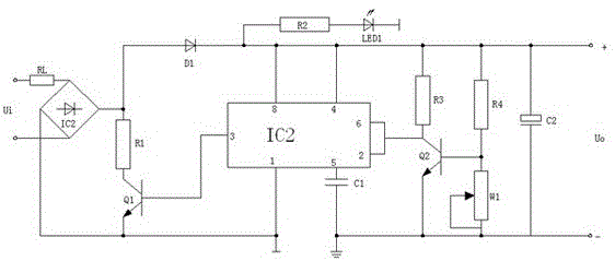
[0025] The electronic switch circuit with capacitor filter output and isolated front and rear stages uses capacitors as the output filter circuit, which can reduce design and application costs and achieve a good filter effect, and is equipped with an indicator light circuit, which can observe the AC rectification output in real time Whether the working status of the final circuit is running normally, and form a detection node for the inspection of the front and rear stages, such as figure 1 As shown, the following structure is specially set up: an input terminal Ui, a load RL, a rectification circuit and an electronic switch circuit are provided, one end of the input terminal Ui is connected to the first terminal of the input terminal of the rectification circuit through the load RL, and the input terminal The other end of Ui is connected to the second end of the input end of the rectification circuit; a control circuit and an output filter circuit are arranged in the electroni...

Embodiment 2

[0028] This embodiment is further optimized on the basis of the above-mentioned embodiments, further to better realize the present invention, such as figure 1 As shown, the following arrangement structure is adopted in particular: integrated chip IC1, capacitor C1, transistor Q2, collector bias resistor R3, pull-up resistor R4, pull-down resistor W1 are arranged in the control circuit, and pin 3 of the integrated chip IC1 , pin 8 and pin 1 are connected to the output terminal of the rectifier circuit; the collector of transistor Q2 is connected with pin 2 and pin 6 of integrated chip IC1, and the collector of transistor Q2 is connected to the second terminal of collector bias resistor R3 On the end, the first end of the collector bias resistor R3 is connected to the 8-pin of the integrated chip IC1, the first end of the pull-up resistor R4 and the first end of the capacitor C2, and the second end of the pull-up resistor R4 is connected to the pull-down The first end of the res...

Embodiment 3

[0030] This embodiment is further optimized on the basis of any of the above embodiments, further to better realize the present invention, such as figure 1 As shown, the following arrangement structure is particularly adopted: the rectifier circuit is provided with a rectifier bridge IC2, a diode D1, a resistor R1 and an electronic switch tube Q1, and one end of the input terminal Ui passes through the load RL and the first input terminal of the rectifier bridge IC2. One end is connected, and the other end of the input end Ui is connected with the second end of the input end of the rectifier bridge IC2; the output end of the rectifier bridge IC2 is respectively connected with the first end of the resistor R1 and the emitter of the electronic switch tube Q1, and the resistor The second end of R1 is connected to the collector of the electronic switch tube Q1, and the first end of the resistor R1 is connected to the 8-pin of the integrated chip IC1 through the diode D1; the base o...


PUM


Abstract

The invention discloses an electronic switch circuit that adopts capacitor filter output and is isolated from the front and rear stages. It is provided with an input terminal Ui, a load RL, a rectifier circuit and an electronic switch circuit. One end of the input terminal Ui passes through the connection between the load RL and the input terminal of the rectifier circuit. The first end is connected, and the other end of the input terminal Ui is connected to the second end of the input end of the rectifier circuit; the ground terminal of the input terminal of the control circuit is isolated from the ground terminal of the output filter circuit; on the output terminal of the rectifier circuit An indicator light circuit is also provided, and the resistance R1 and LED1 connected in series are arranged in the indicator light circuit, and the ground terminal of the indicator light circuit is connected with the ground terminal of the input terminal of the control circuit; the capacitor is used as the output filter circuit to reduce the design and While applying cost, it has a good filtering effect. It is equipped with an indicator circuit to observe in real time whether the working status of the circuit after the AC rectification output is normal, and to form a detection node for the inspection of the front and rear stages.

Description

technical field [0001] The invention relates to the technical field of electronic circuits, in particular, it is an electronic switch circuit which adopts capacitance filter output and isolates the front and rear stages. Background technique [0002] An electronic switch refers to an operating unit that uses electronic circuits and power electronic devices to realize circuit switching, including at least one controllable electronic drive device, such as thyristors, transistors, field effect transistors, thyristors, relays, etc. However, in actual use, electronic switches mainly refer to wall switches such as touch switches, induction switches, voice-activated switches, and wireless switches. [0003] The 555 timer is a medium-scale integrated device that combines analog and digital functions. Generally, the bipolar (TTL) process is called 555, and the complementary metal oxide (CMOS) process is called 7555. In addition to the single timer, there are corresponding dual timer...

Claims


Application Information

Patent Timeline
Patent Type & Authority Applications(China)
IPC IPC(8): H03K17/16H03K17/18H03K17/567
CPCH03K17/16H03K17/18H03K17/567
Inventor 杨素贤
Owner 成都立威讯科技有限公司
Why Eureka
Try Eureka