Recording medium having a substrate containing microscopic pattern of parallel groove and land sections and recording/reproducing equipment therefor

a technology of parallel grooves and recording media, which is applied in the direction of optical recording/reproducing/erasing methods, recording signal processing, instruments, etc., can solve the problems of excessive loss of information, damage to information recorded in adjacent tracks, and increase in coma aberration, so as to improve the cross erase phenomenon and increase the density

Inactive Publication Date: 2006-11-07
JVC KENWOOD CORP
View PDF21 Cites 43 Cited by
  • Summary
  • Abstract
  • Description
  • Claims
  • Application Information

AI Technical Summary

Problems solved by technology

However, coma aberration also increases extremely when an information recording medium is slanted.
If the cross erase phenomenon occurs, as mentioned above, an information recorded in an adjacent track is damaged.
In a case of an information system having larger capacity, an amount of lost information becomes excessively large.
Consequently, affection to a user is enormous.

Method used


Image

  • Recording medium having a substrate containing microscopic pattern of parallel groove and land sections and recording/reproducing equipment therefor
  • Recording medium having a substrate containing microscopic pattern of parallel groove and land sections and recording/reproducing equipment therefor
  • Recording medium having a substrate containing microscopic pattern of parallel groove and land sections and recording/reproducing equipment therefor

Examples


first embodiment

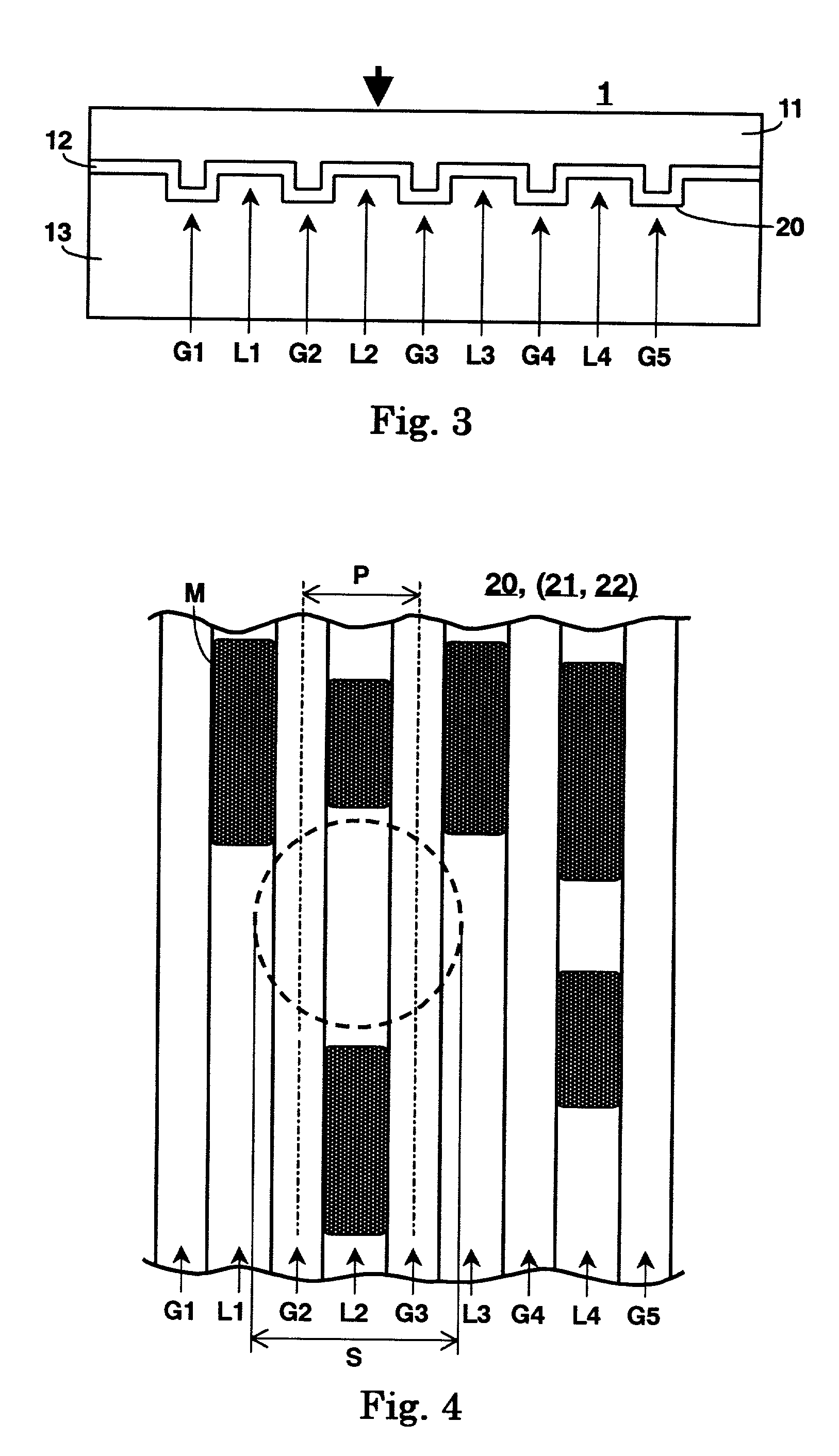
[0049]With referring to FIGS. 3 and 4, an information recording medium according to a first embodiment of the present invention will be explained.

[0050]FIG. 3 is a cross sectional view of an information recording medium according to a first embodiment of the present invention.

[0051]FIG. 4 is a fragmentary plan view, partially enlarged, of the information recording medium shown in FIG. 3.

[0052]In FIG. 3, an information recording medium 1 is at least composed of a recording layer 12 and a light transmission layer 11, which are formed and laminated on a substrate 13 formed with a rugged microscopic pattern 20 in order. Ruggedness of the microscopic pattern 20 is almost in a shape of continuous substance of parallel grooves G1 through G5 (hereinafter generically referred to as groove section G), wherein a plurality of land L1 through L4 (hereinafter generically referred to as land section L) is provided between the groove sections G.

[0053]The information recording medium 1 is a read onl...

second embodiment

[0090]With referring to FIG. 5, an information recording medium according to a second embodiment of the present invention is explained.

[0091]FIG. 5 is a cross sectional view of an information recording medium according to a second embodiment of the present invention.

[0092]In FIG. 5, same compositions as those of the first embodiment shown in FIG. 3 are indicated by the same sign as that of the first embodiment respectively and their explanations are omitted.

[0093]As shown in FIG. 5, an information recording medium 2 is the same configuration as that of the first embodiment except for the light transmission layer 11. A light transmission layer of the second embodiment is composed of a light transmission layer 11a and an adhesive light transmission layer 11b.

[0094]The light transmission layer 11a is identical to the light transmission layer 11 of the first embodiment. On the contrary, the adhesive light transmission layer 11b is a layer for adhering the light transmission layer 11a t...

third embodiment

[0099]With referring to FIG. 6, an information recording medium according to a third embodiment of the present invention is explained.

[0100]FIG. 6 is a cross sectional view of an information recording medium according to a third embodiment of the present invention.

[0101]In FIG. 6, same compositions as those of the first embodiment shown in FIG. 3 are indicated by the same sign as that of the first embodiment respectively and their explanations are omitted.

[0102]As shown in FIG. 6, an information recording medium 3 is the same configuration as that of the first embodiment except for a resin layer 14 formed with a microscopic pattern 21. The information recording medium 3 is composed of the resin layer 14 formed with the microscopic pattern 21, a recording layer 12 and a light transmission layer 11, which are laminated on a substrate 13a in order.

[0103]In the information recording medium 3 according to the third embodiment of the present invention, forming the microscopic pattern 21 o...


PUM

PropertyMeasurementUnit
thicknessaaaaaaaaaa
wavelengthaaaaaaaaaa

Abstract

An information recording medium 1 at least comprises a substrate 13 having a microscopic pattern 20, which is constituted by a shape of continuous substance of approximately parallel grooves formed with a groove section G and a land section L alternately, a recording layer 12 formed on the microscopic pattern 20 and a light transmission layer 11 formed on the recording layer. The microscopic pattern 20 is formed so as to satisfy a relation of P<λ / NA and a thickness of the light transmission layer 11 is within a range of 0.07 to 0.12 mm, wherein P is a pitch of the groove section G or the land section L, λ is a wavelength of reproducing light beam and NA is a numerical aperture of an objective lens. Further, there provided an information recording medium, which is improved in cross erase and recorded in high density, and a reproducing apparatus and a recording apparatus for the information recording medium.

Description

BACKGROUND OF THE INVENTION[0001]1. Field of the Invention[0002]The present invention relates to an information recording medium, a reproducing apparatus and a recording apparatus, which reads out information from the information recording medium which moves, and particularly relates to an information recording medium to be recorded and / or reproduced through an optical device, and a reproducing apparatus and a recording apparatus for such an information recording medium.[0003]2. Description of the Related Art[0004]Until now, there is existed a system for reading out information from an information recording medium, which moves. In such a system, reproduction is performed by using a device such as an optical device, a magnetic device and a capacitive device. A system, which records and / or reproduces by an optical device, is used extensively in daily living. With respect to a read only information recording medium to be reproduced by using a light beam having a wavelength λ of 650 nm,...

Claims


Application Information

Patent Timeline
Patent Type & Authority Patents(United States)
IPC IPC(8): G11B7/24G11B7/0045G11B7/007G11B7/246G11B20/10
CPCG11B7/00718G11B7/24079G11B7/24082G11B20/10G11B7/0045G11B7/246
Inventor KONDO, TETSUYAOISHI, KENJI
Owner JVC KENWOOD CORP
Why Eureka
Try Eureka