Reflection detection in an optical wireless link

a technology of optical wireless link and reflection detection, which is applied in the direction of electromagnetic transmission, electrical equipment, transmission, etc., can solve the problems of limited distance that such high-frequency communications can travel, physical installation and maintenance costs, and the deployment of each of these conventional communications facilities involves certain limitations, so as to achieve the effect of minimal additional computational and data overhead and minimal time required for transmitting additional data

Active Publication Date: 2006-11-07
TEXAS INSTR INC
View PDF5 Cites 16 Cited by
  • Summary
  • Abstract
  • Description
  • Claims
  • Application Information

AI Technical Summary

Benefits of technology

[0014]The present invention provides a number of advantages. For example, use of a preferred embodiment of the present invention permits the detection of a reflected light beam by a receiver where the light beam originated from a transmitter that is part of the same optical wireless link as the receiver with a minimum of additional computational and data overhead.
[0015]Also, use of a preferred embodiment of the present invention does not require the

Problems solved by technology

Each of these conventional communications facilities involves certain limitations in their deployment.
In the case of communications over the telephone network, high-speed data transmission, such as that provided by digital subscriber line (DSL) services, must be carried out at a specific frequency range so as to not interfere with voice traffic, and is currently limited in the distance that such high-frequency communications can travel.
This physical installation and maintenance is costly, as well as limiting to the user of the communications network.
Conventional wireless technologies involve their own limitations, however.
Furthermore, current wireless telephone communication of large data blocks, such as video, is prohibitively expensive, considering the per-unit-time charges for wireless services

Method used


Image

  • Reflection detection in an optical wireless link
  • Reflection detection in an optical wireless link
  • Reflection detection in an optical wireless link

Examples


Embodiment Construction

[0026]The making and use of the various embodiments are discussed below in detail. However, it should be appreciated that the present invention provides many applicable inventive concepts, which can be embodied in a wide variety of specific contexts. The specific embodiments discussed are merely illustrative of specific ways to make and use the invention, and do not limit the scope of the invention.

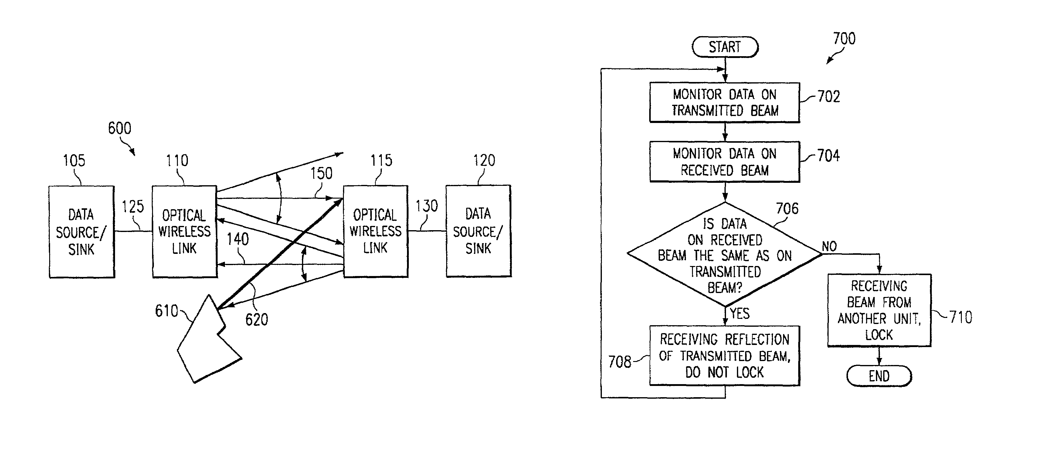
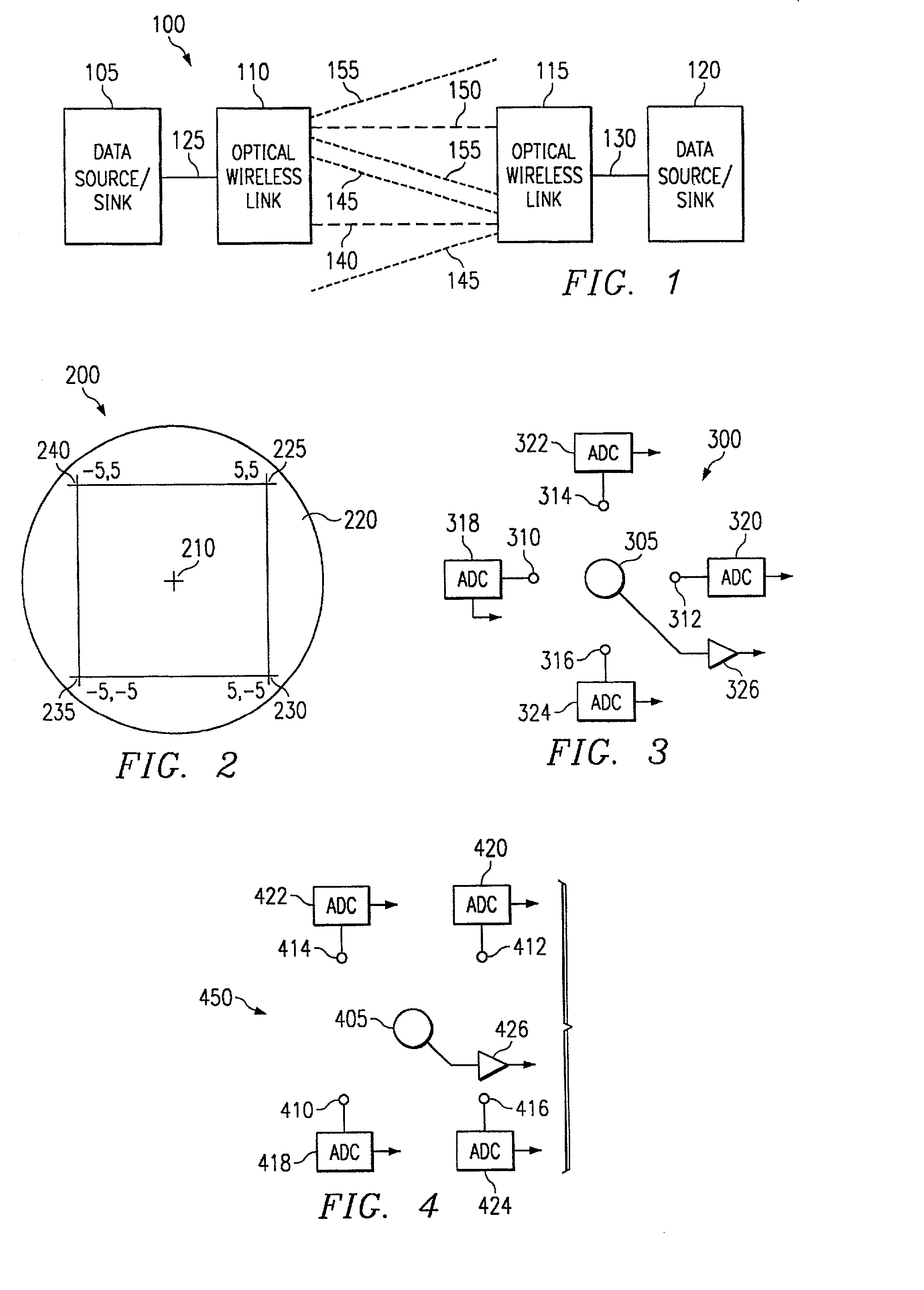
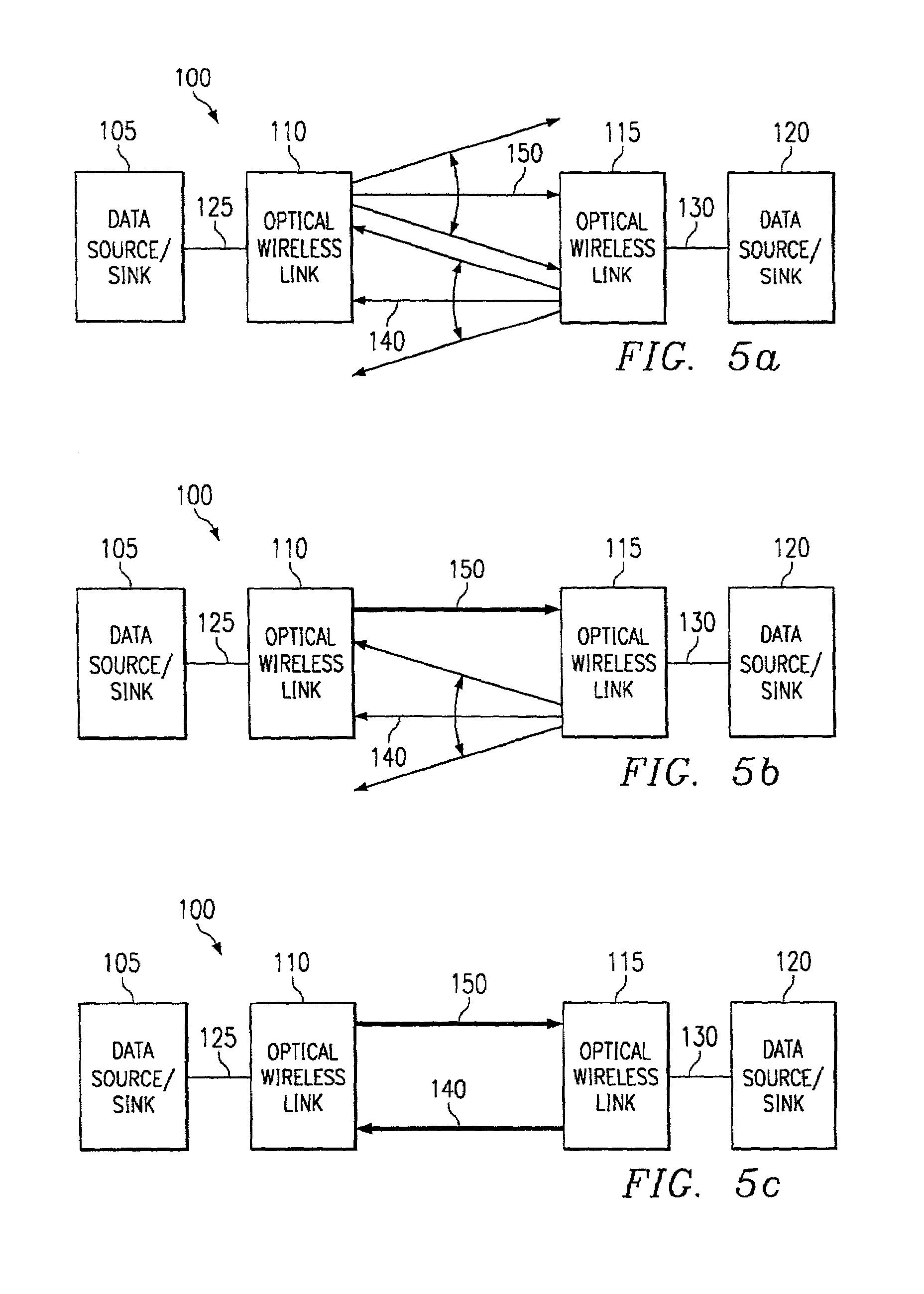
[0027]FIG. 1 illustrates a preferred embodiment optical wireless system 100, including a first data source / sink 105 connected to a first Optical Wireless Link (“OWL”) 110. The OWL 110 can both transmit to and receive data from a second OWL 115 over a wireless optical path. The second OWL 115 is in turn connected to a second data sink / source 120. Preferably each OWL device is an optical path-to-sight modem. As used herein, the term path-to-sight is intended to mean an unobstructed optical path (which may include reflections) generally through the ether, as contrasted with through an optic ...


PUM


Abstract

In an optical wireless network, where light beams are transmitted over-the-air, reflections of the transmitted light beams may cause a receiver of an optical wireless device to detect and subsequently lock onto the signal that it transmitted. By doing so, the network is effectively broken. A method and apparatus to detect the reception of reflected signals using minimal additional hardware and data is presented. Should a reflected signal be detected, the receiver is prevented from locking onto the signal, allowing the receiver to detect and subsequently lock onto light beams originating from other optical wireless devices.

Description

CROSS REFERENCE TO RELATED APPLICATION[0001]The following co-pending, co-assigned patent applications are related to the present invention. Each of the applications is incorporated herein by reference.[0002]Ser. No.Filing DateAttorney Docket60 / 234,0819 / 20 / 2000TI-3144460 / 233,8519 / 20 / 2000TI-3161209 / 839,6904 / 20 / 2001TI-3142909 / 923,5108 / 6 / 2001TI-3144060 / 285,4614 / 20 / 2001TI-32924FIELD OF THE INVENTION[0003]This invention relates generally to optical wireless communications, and more specifically, to detecting self-reflections of transmissions on optical wireless links.BACKGROUND OF THE INVENTION[0004]Modern data communications technologies have greatly expanded the ability to communicate large amounts of data over many types of communications facilities. This explosion in communications capability not only permits the communications of large databases, but has also enabled the real-time (and beyond) digital communications of audio and video content. This high bandwidth communication is now...

Claims


Application Information

Patent Timeline
IPC IPC(8): H04B10/00G02B6/35H04B10/10
CPCH04B10/11H04B10/1123H04B10/1125
Inventor OETTINGER, ERIC GREGORYHEMINGER, MARK DAVID
Owner TEXAS INSTR INC
Why Eureka
Try Eureka