Providing a presentation on a network

a network and presentation technology, applied in the field of networked presentation systems, can solve the problems of still substantial expense in conducting such a teleconference, and the maintenance of dedicated telepresentation centers is expensiv

Inactive Publication Date: 2006-11-07
RED HAT
View PDF158 Cites 78 Cited by
  • Summary
  • Abstract
  • Description
  • Claims
  • Application Information

AI Technical Summary

Benefits of technology

[0041]The present invention allows confidential presentation data to be kept within a corporate intranet behind a firewall (i.e., a network security feature that restricts communications with devices not included in the intranet, and in particular, that restricts the access to data stored within the intranet). Thus, the present invention allows a show or presentation to be controlled externally from the firewall, while at least the confidential data remains within the firewall and is presented to only those within the firewall under the direction of a leader that is potentially outside the firewall. Further, because the present invention employs a “client-request” technology, where each presentation member's browser requests information from a communications network server, typically data transmissions in response to such requests are not blocked by most firewalls.

Problems solved by technology

However, there is still substantial expense in conducting such a telepresentation, particularly when the presentation members (i.e., presentation leaders and audience members) reside at a large number of geographically scattered sites.
Thus, due to the expense of provisioning and maintaining such networked conferencing systems, corporations typically have only a small number of such conferencing systems at strategically located telepresentation centers for conducting such telepresentations.
However, there are numerous drawbacks to this approach, such as:(1.1) The dedicated telepresentation centers are expensive to maintain;(1.2) Presentation participants are still required to travel to these centers; and(1.3) Potential members of such a presentation who are not able to access such a center are excluded from the presentation.

Method used


Image

  • Providing a presentation on a network
  • Providing a presentation on a network
  • Providing a presentation on a network

Examples


Embodiment Construction

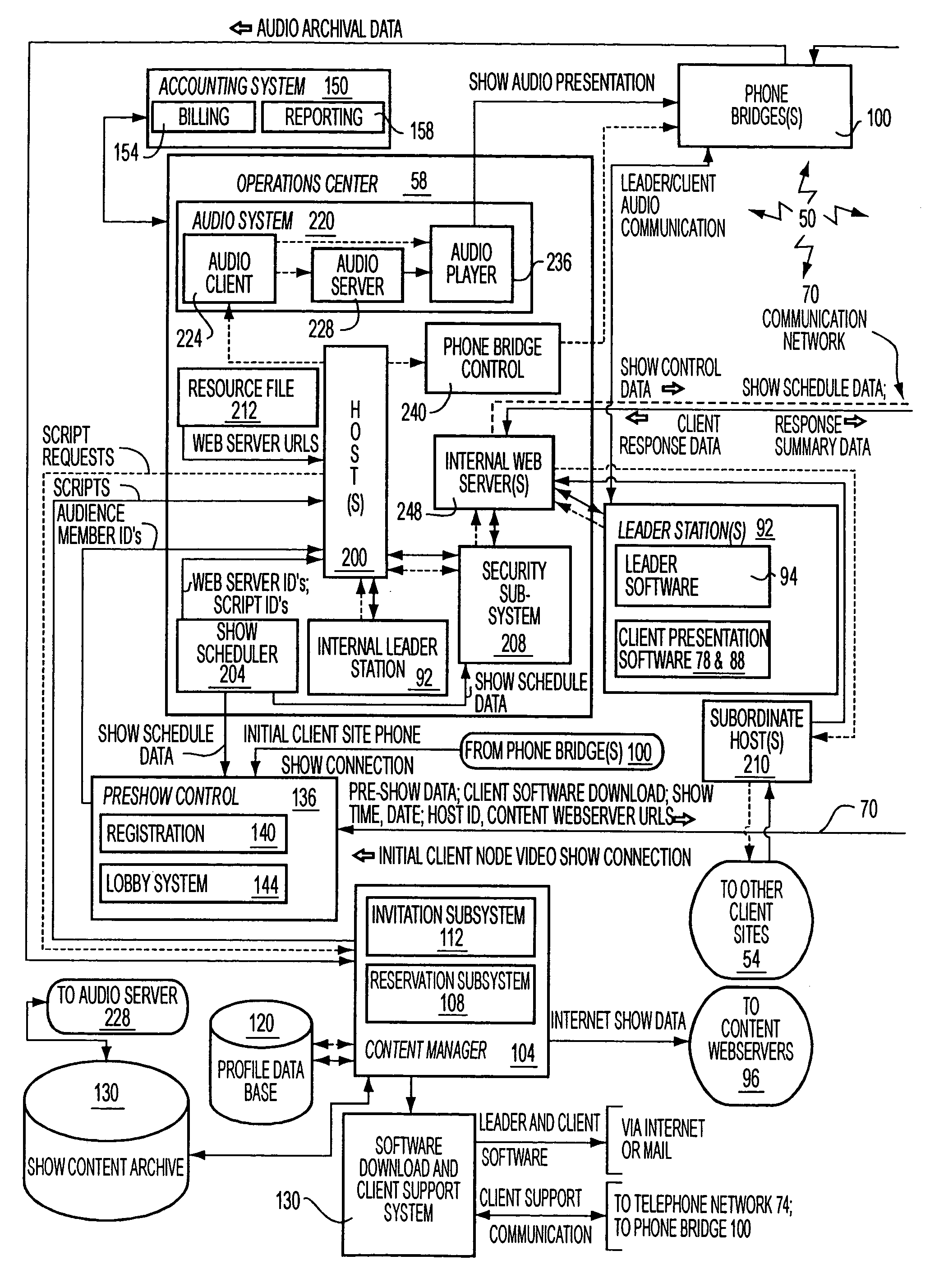
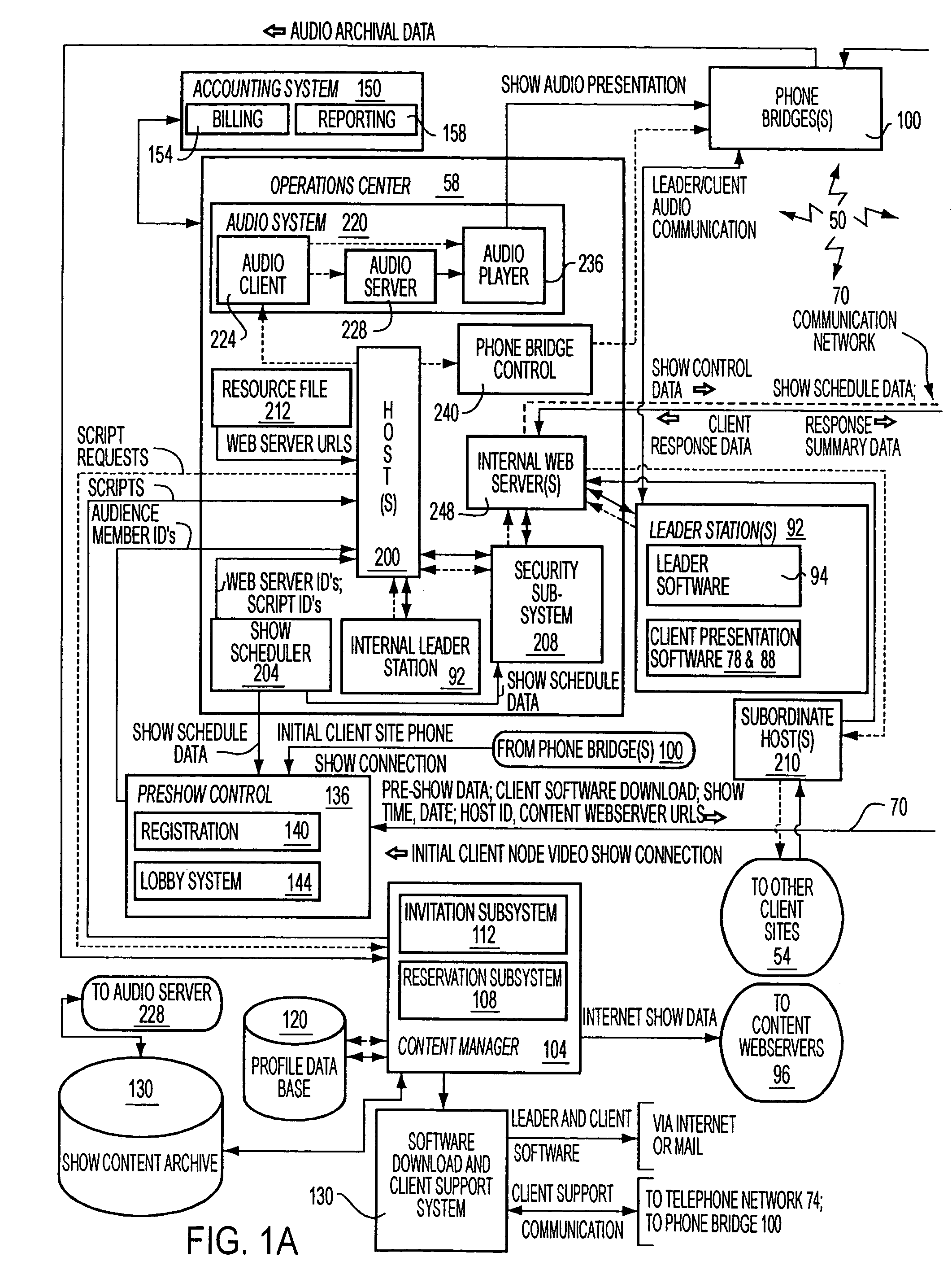
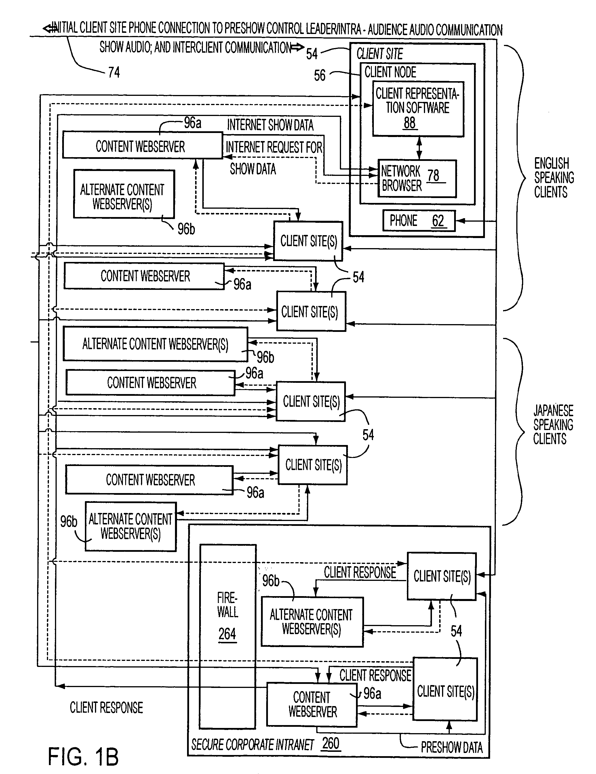
[0046]In FIG. 1, a block diagram illustrating the components of the presentation system 50 of the present invention is provided, wherein solid arrows denote presentation data flows and dashed arrows denote control data flows. Note that the presentation system 50 utilizes the following high-level components:[0047](4.1) Client Sites 54[0048]Client sites 54, where audience members receive a presentation. Typically, at least some of the client sites 54 are sufficiently geographically dispersed so that a face-to-face presentation is not possible. Additionally, note that each client site 54 has at least one of a client node 56 (e.g., a personal computer), and a telephone 62, wherein the client node 56 may receive video (and possibly audio as well) information from a communications network 70 such as the Internet, and the phone 62 may be used for receiving an audio portion of the presentation routed separately through one or more voice grade telephony networks (collectively labeled 74). Ac...


PUM


Abstract

A presentation system is disclosed for distributing a performance of a presentation synchronously to a plurality of client nodes on a network such as the Internet. The presentation system distributes presentation content data to a plurality of network server nodes, and during a performance of the presentation, the client nodes receiving the presentation determine a particular variation of data presentation to retrieve from the network server nodes. In particular, the retrieval of presentation data depends upon the transmission characteristics of the network such as data transmission rate. Thus, if a low transmission data rate is detected at a first client node, presentation elements of a reduced size can be retrieved. Alternatively, if a higher transmission rate is detected at a second client node, presentation elements of greater size (and corresponding enhanced quality of presentation) can be retrieved. Thus, within a single performance, client network nodes with varying available network bandwidths can be utilized for synchronously and simultaneously performing the presentation.

Description

CROSS REFERENCE TO RELATED APPLICATION[0001]The present application is a Continuation application of prior application U.S. patent application Ser. No. 09 / 675,527 filed Sep. 29, 2000, now U.S. Pat. No. 6,598,075 which is a continuation of U.S. patent application Ser. No. 09 / 052,862 filed Mar. 31, 1998 (now U.S. Pat. No. 6,161,137), which claims the benefit of U.S. Provisional Patent Application Ser. No. 60 / 041,770 filed Mar. 31, 1997. The entire disclosure of the prior applications are considered to be part of the disclosure of the present application and are hereby incorporated by reference.FIELD OF THE INVENTION[0002]The present invention relates to a networked presentation system for providing a presentation to a plurality of client nodes on a communications network such as the Internet, and more particularly to a presentation system wherein network transmission characteristics are utilized in determining the presentation materials presented at each client node during a performan...

Claims


Application Information

Patent Timeline
Patent Type & Authority Patents(United States)
IPC IPC(8): G06F15/16H04L12/18H04L12/28H04L29/06H04L29/08H04N7/15H04N21/2343H04N21/24H04N21/2662H04N21/4402
CPCH04L12/1813H04L12/1822H04L12/1827H04L12/5692H04L29/06H04L29/06027H04L63/0428H04L63/083H04N7/15H04N21/234327H04N21/2402H04N21/2662H04N21/440227H04L65/4084H04L65/80H04L67/2823H04L67/2819H04L67/2828H04L67/02H04L67/28H04L12/1836H04L63/02H04L63/04H04L67/2842H04L69/329H04L65/612H04L67/56H04L67/564H04L67/565H04L67/5651H04L67/568H04L9/40H04L65/1101
Inventor OGDON, ROBERT H.JOHNSON, FRANK E.
Owner RED HAT
Why Eureka
Try Eureka