
Fluid level measuring device having at least one compressible member

a technology of fluid level measurement and compressible member, which is applied in the direction of liquid/fluent solid measurement, machines/engines, instruments, etc., can solve the problems of increasing the number of fluid level indicators, increasing the cost of fluid level indicators, and increasing the number of fluid access routes or paths through which fluid level indicators system accesses fluid storage compartments, etc., to achieve easy manual motion, easy to use, and positive engagement

Inactive Publication Date: 2006-11-14
ORSCHELN PRODS
View PDF15 Cites 10 Cited by
  • Summary
  • Abstract
  • Description
  • Claims
  • Application Information

AI Technical Summary

Benefits of technology

[0009]In one aspect of the invention, the handle associated with a dipstick that be free to swivel or rotate freely within a plastic handle (i.e., the dipstick / shaft can rotate relative to the handle). By being able to rotate (e.g., while being inserted through a non-liner tube and into an engine component), the dipstick can accommodate travel along non-liner routes without binding or being permanently deformed.
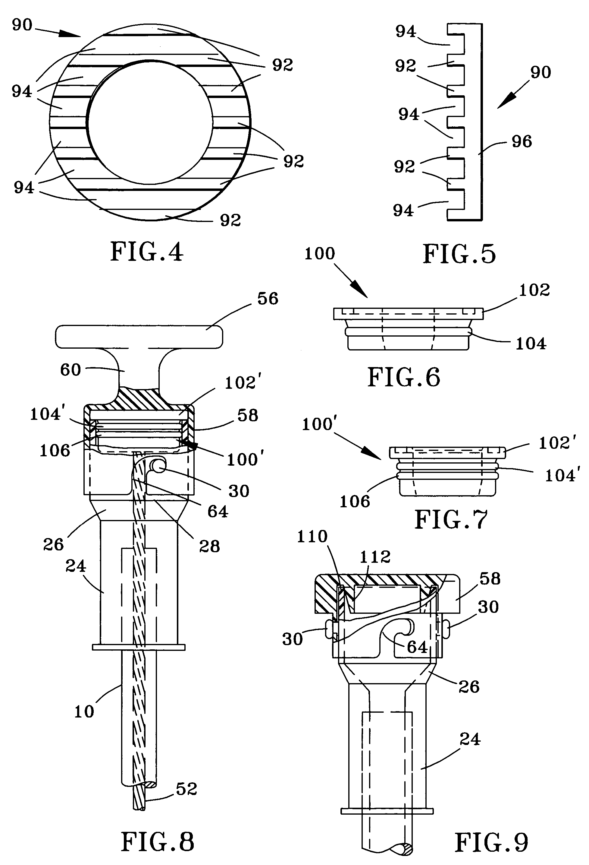
[0014]The bayonet interconnection in unison with the gasket can supply an actual pressurized seal thereby allowing pressurized testing of the combustion engine, transmission, or other machinery without either removal of the dipstick or attempts at sealing the dipstick. Furthermore, a sealed dipstick allows the combustion engine, transmission, or other machinery to run at the intended pressure rather than either below the intended pressure or at the intended pressure due to an adjustment. The seal and locking engagement between the handle and enlarged end typically involves a quarter-turn sealing motion with an improved sealing capability and a positive lock feature. Alternatively, the bayonet interconnection seal releases pressure and allows the system to be vented (e.g., fluid level indicators for transmissions can be vented by using, for example, the gasket of FIGS. 4 and 5).
[0015]The structure is normally manufactured from lightweight, corrosion-resistant, plastic materials such as nylon, glass-reinforced nylon, steel and steel alloys (e.g., 1008, 1010, and silicon or aluminum killed draw quality alloys), among other oil, water and temperature resistant materials. A metallic shaft can be fabricated from stainless steel, zinc plated, phosphated, chromated, among other metal treatments to improved corrosion resistance.
[0018]In a further aspect, the invention provides a smaller and more compact fluid level indicating system which has improved flexibility for routing of the fluid level indicator system in and around the complex design of engines, transmissions, and machinery.
[0019]The instant invention can also be employed as a kit or an assemblage in order to retrofit existing dipstick systems. When employed as a retro-fit, the inventive dipstick system provides the same advantages as if installed as an original equipment dipstick.
[0020]Regardless of whether the aspects of the invention are employed alone or in combination, the instant invention provides a more corrosion-resistant, lighter weight, less complex, higher precision and more cost effective fluid level indicator system.

Problems solved by technology

The actual assembly of these various components involves multiple assembly operations requiring costly, time-consuming, and labor intensive manufacturing steps.
Moreover, the fluid access routes or paths through which the fluid level indicator system accesses the fluid storage compartments are becoming more complex (more twists and turns as well as longer runs), smaller, and more compact.
Variations in the length of a shaft associated with a fluid level indicator blade can cause overextension or under-extension of the blade into the reservoir thereby providing an inaccurate reading on the blade.

Method used


Image

  • Fluid level measuring device having at least one compressible member
  • Fluid level measuring device having at least one compressible member
  • Fluid level measuring device having at least one compressible member

Examples


Embodiment Construction

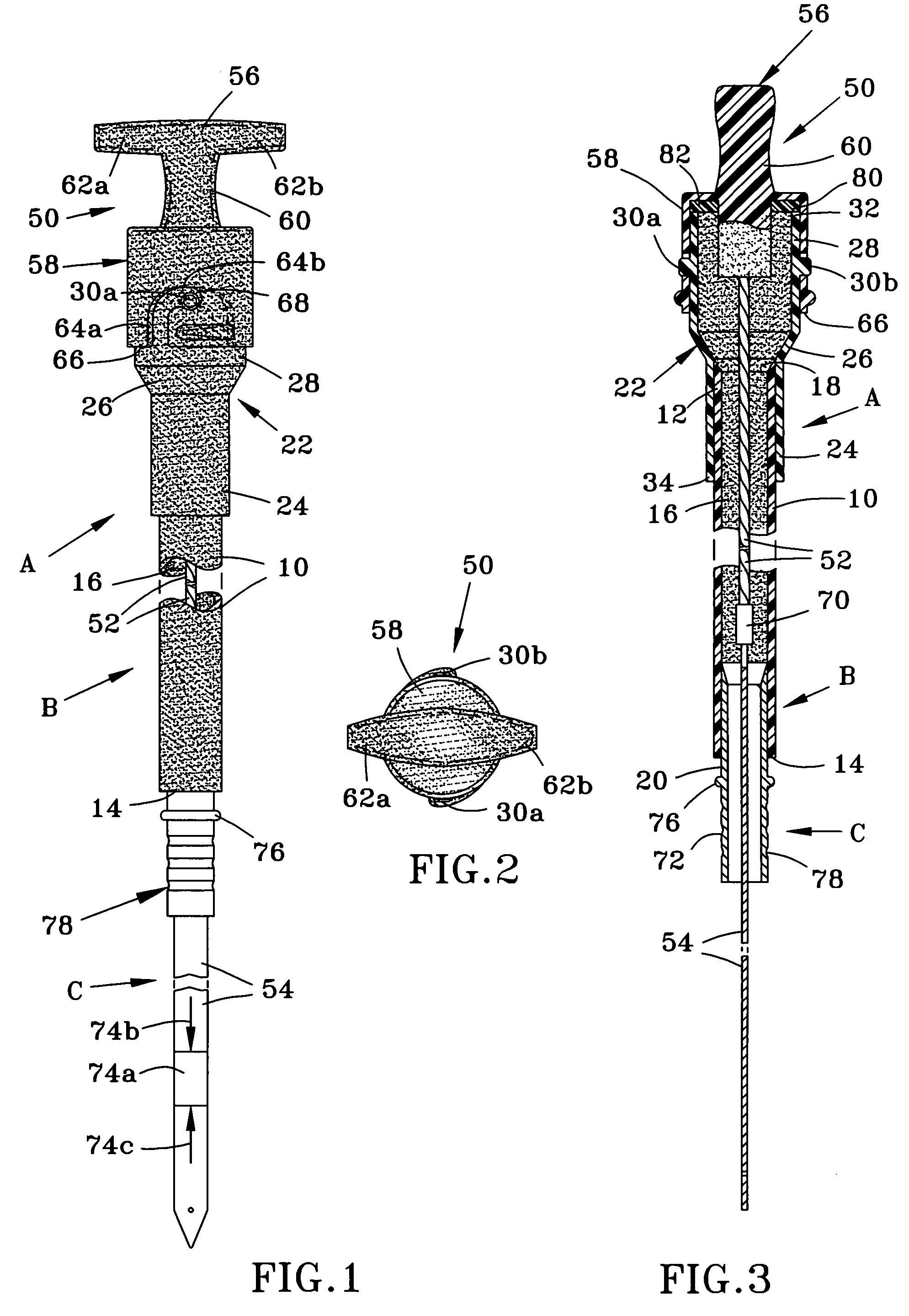
[0045]The instant invention relates to a fluid level measuring device comprising a tube having lugs extending therefrom that engage slots defined in a handle. The lugs can be either inwardly or outwardly extending and are dimensioned to be received by the slotted handle. The handle is associated with a shaft having a dipstick for measuring fluid level. At least a portion of the shaft comprises a compressible member. The shaft further comprises an enlarged region for engaging a protuberance defined by the tube.

[0046]In a first aspect of the invention, the fluid level measuring device comprises a handle having at least one slot defined therein and a shaft having an associated dipstick, a tube having lugs directly attached to the tube and dimensioned to engage the slotted handle, and a compressible gasket or grommet associated with the handle. When the lugs engage the slots, the gasket or grommet can urge the handle and tube into a locked position.

[0047]One aspect of the instant invent...


PUM


Abstract

A fluid level measuring device, also referred to as a dipstick, for measuring the fluid level in a fluid reservoir or tank, such as an oil pan or transmission reservoir in an internal combustion engine. The fluid level measuring device includes a stationary tube onto which lugs can be directly attached. The dipstick assembly includes a fluid level indicator measuring blade attached to an elongated shaft that is molded into a plastic handle assembly. The plastic handle assembly includes a bayonet type locking mechanism for locking the handle to the stationary tube assembly. A compressible seal forms a pressurized seal between the stationary tube assembly and the handle.

Description

[0001]This Application claims benefit of Provisional U.S. Patent Application Ser. No. 60 / 435,642, filed on Dec. 20, 2002. The disclosure of the provisional patent application is hereby incorporated by reference.FIELD OF THE INVENTION[0002]The subject invention is directed to a device used to measure fluid levels, and more particularly, to dipsticks used to measure fluid levels by contacting an indicator at one end of the dipstick into a fluid holding compartment or reservoir.BACKGROUND OF THE INVENTION[0003]It is known to use a fluid measuring device for indicating the fluid level in a selected fluid holding compartments of internal combustion engines, transmissions, and other machinery requiring fluids for lubrication and cooling. Typically, the fluid measuring device is a dipstick for checking the level of fluid such as engine or transmission oil, or hydraulic fluid within one of the many fluid holding compartments in the engine, transmission, or other machine. The dipstick is nor...

Claims


Application Information

Patent Timeline
IPC IPC(8): G01F23/04
CPCG01F23/04
Inventor PORTER, CURTIS H.DOUGHERTY, JOHN M.MAREK, STEVEHALFERTY, MICHAELTAYON, JEFF
Owner ORSCHELN PRODS
Learn More