Cutting segment, method of manufacturing cutting segment, and cutting tool

a cutting tool and cutting technology, applied in the direction of gear teeth, manufacturing tools, manufacturing apparatus, etc., can solve the problems of deteriorating cutting efficiency of cutting tools, reducing cutting efficiency of diamond particles, and reducing life span, so as to reduce manufacturing costs, improve cutting capability, and simplify manufacturing process

Inactive Publication Date: 2006-11-14
NIWA DAIYAMONDO INDS
View PDF2 Cites 32 Cited by
  • Summary
  • Abstract
  • Description
  • Claims
  • Application Information

AI Technical Summary

Benefits of technology

[0024]The present invention has been made to solve the above problems, and it is an object of the present invention to provide a cutting segment, which uses a metal plate instead of a powdered metal as a matrix, thereby realizing an excellent cutting capability, a simplified manufacturing process and remarkably reduced manufacturing costs.

Problems solved by technology

As mentioned above, when the diamond particles are mixed with the metal powders, the diamond particles are not uniformly distributed among the metal powders, resulting in a decrease in cutting efficiency of the diamond particles and reduction in life span.
That is, when mixing the diamond particles and the metal powders acting as the matrix, differences in sizes and specific gravities between the particles cause segregation of the diamond particles, thereby generating non-uniform distribution of the diamond particles among the metal powders.
When the diamond particles are segregated as described above, not only is the cutting efficiency of the cutting tool deteriorated, but the life span of the cutting tool is also reduced.
Although the patterning technology for the diamond particles can solve the problems caused by segregation of the diamond particles, intrinsic problems caused by the use of the powdered metal matrix cannot be solved.
During the process of compacting the metal matrix, due to severe wear of compaction die by the diamond particles, there frequently occurs a variation in thickness of the matrix or a breakage of the matrix, thereby lowering productivity.
Furthermore, in severe cases, dimensions of the matrix are changed, so that the segments have different dimensions, respectively, resulting in performance variation and deterioration of the diamond tool.
Further, even though the metal powders for the matrix can be manufactured by various methods using the same components, manufacturing costs of the metal powders are remarkably high compared with a bulk of metal, such as plate, coil, rod, and the like.

Method used


Image

  • Cutting segment, method of manufacturing cutting segment, and cutting tool
  • Cutting segment, method of manufacturing cutting segment, and cutting tool
  • Cutting segment, method of manufacturing cutting segment, and cutting tool

Examples


example 1

[0129]In order to investigate cutting capability and life span of a cutting tool according to the present invention, a cutting test was conducted for a saw blade (Inventive material 3) manufactured according to the present invention and for the other saw blade (Conventional material 2) manufactured according to the conventional method, and results of the test are shown in Table 2 as follows.

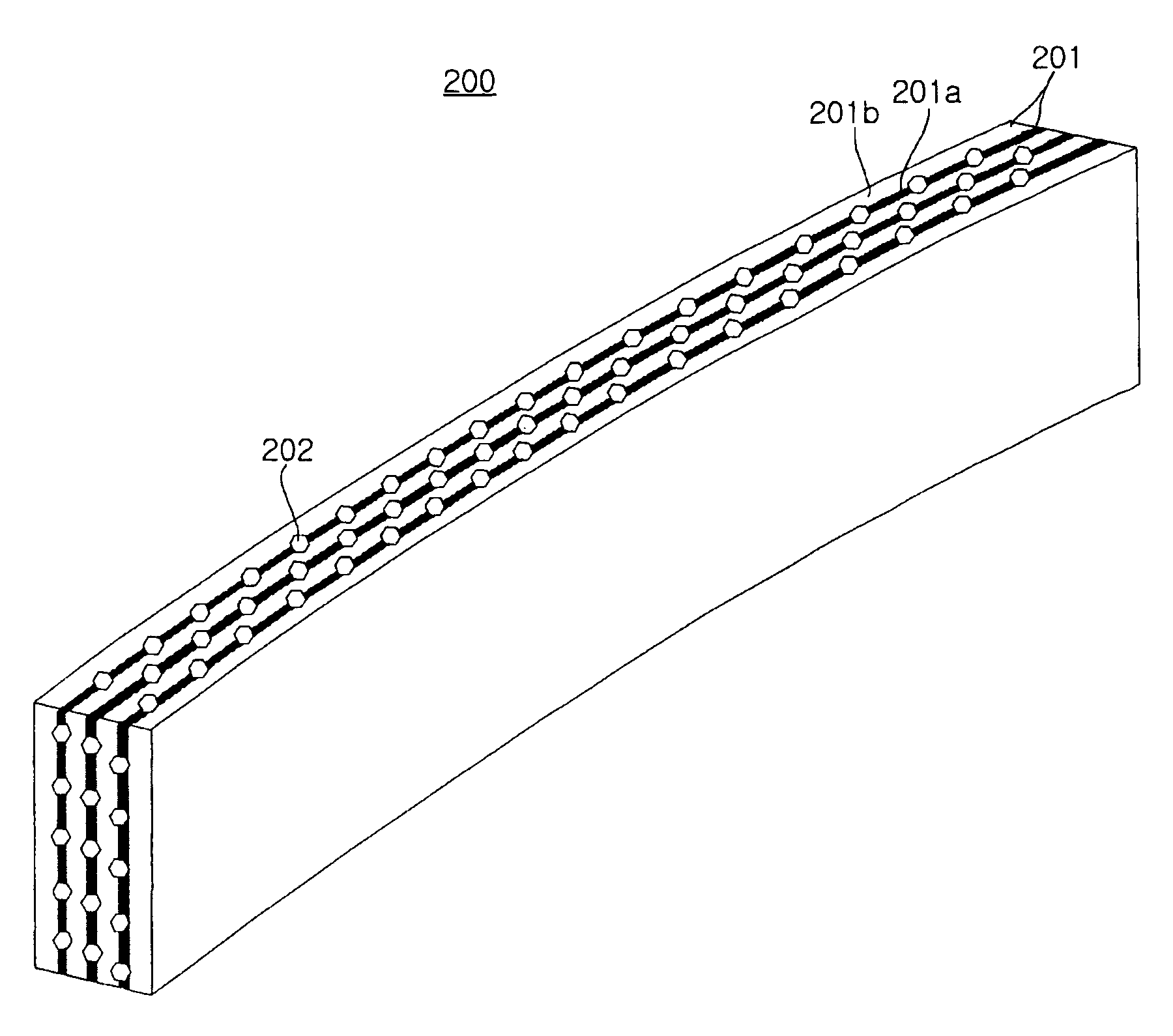
[0130]In Table 2, Inventive material 3 was manufactured by laminating four SK85 steel plates, each having a thickness of 0.5 mm, followed by arranging two metal preforms made of 100% Co between the steel plates and arranging a tape with diamond particles uniformly arranged between the metal preforms. Conventional material 2 was manufactured by mixing the diamond particles and the metal powders.

[0131]The diamond particles used in Example 1 were MBS 955 available from GE in the U.S.A.

[0132]Sintering was performed at a sintering temperature of 950° C. for 5 minutes by hot pressing.

[0133]For the cutt...

example 2

[0138]Changes in cutting time depending on the number of cutting cycles were investigated by a cutting test on the washed concrete using the saw blades of Inventive material 3 and Conventional material 2 of Example 1, and results of the test are shown in FIG. 10.

[0139]The term “cutting time” means the time taken for the saw blade to cut a workpiece one time in a cutting operation. The term “cutting one time” means that the workpiece having a length of 30 cm is cut one time in a predetermined depth.

[0140]As shown in FIG. 10, it can be appreciated that the saw blade of Inventive material 3 has a more reduced cutting time, a more stable tendency of the cutting time, and a more uniform capability than the saw blade of Conventional material 2.

[0141]As is apparent from the above description, according to the present invention, there are advantageous effects in that as the plate-shaped metal matrices are used instead of the powdered matrices when manufacturing the cutting segment, manufact...


PUM

PropertyMeasurementUnit
thicknessaaaaaaaaaa
wt %aaaaaaaaaa
temperatureaaaaaaaaaa

Abstract

A cutting segment for a cutting tool used for cutting or drilling a brittle workpiece, such as stone, brick, concrete and asphalt, a method of manufacturing the segment and a cutting tool provided with the segment are disclosed. The segment comprises a plurality of plate-shaped metal matrix layers laminated perpendicular to a cutting surface of the segment while being parallel to a cutting direction of the segment, the plate-shaped metal matrix layers being integrally combined with each other and made of a ferrous or non-ferrous material; and diamond particle layers arranged between the plate-shaped metal matrix layers such that diamond particles can be provided in an array on the cutting surface. The segment has an excellent cutting capability, and can be made by a simplified manufacturing process, thereby remarkably reducing manufacturing costs.

Description

BACKGROUND OF THE INVENTION[0001]1. Field of the Invention[0002]The present invention relates to a cutting segment for a cutting tool used for cutting or drilling brittle workpieces, such as stone, brick, concrete and asphalt; a method of manufacturing the segment; and a cutting tool comprising the segment. More particularly, the present invention relates to a cutting segment for a cutting tool, which uses a plate-shaped metal matrix instead of a powdered metal matrix, a method of manufacturing the segment, and a cutting tool comprising the segment.[0003]2. Description of the Related Art[0004]In order to cut or dill brittle workpieces, such as stone, brick, concrete and asphalt, it is necessary to provide an abrasive material having hardness higher than that of the workpieces.[0005]Synthetic diamond particles, natural diamond particles, nitrogen boride and cemented carbide are well known in the art as abrasive materials, and particularly, synthetic diamond particles have been most w...

Claims


Application Information

Patent Timeline
Patent Type & Authority Patents(United States)
IPC IPC(8): B28D1/12B23F21/03B23D61/02B24D5/12B24D99/00B28D1/02B28D1/04
CPCB23D61/18B24D99/005B28D1/121A01F7/02A01F11/00A01F12/18A01F12/30
Inventor KIM, SOO-KWANGPARK, HEE-DONG
Owner NIWA DAIYAMONDO INDS
Why Eureka
Try Eureka