Rear view mirror monitor

a monitor and rear view technology, applied in the field of rear view mirror monitors, can solve the problem that the system cannot accurately determine the presence and orientation of the same, and achieve the effect of low cost and low cos

Inactive Publication Date: 2006-11-14
AMERICAN VEHICULAR SCI
View PDF43 Cites 33 Cited by
  • Summary
  • Abstract
  • Description
  • Claims
  • Application Information

AI Technical Summary

Benefits of technology

[0120]40. To provide a vehicle monitoring system using modulated radiation to aid in the determining of the distance from a transducer (either ultrasonic or electromagnetic) to an occupying item of a vehicle.
[0121]41. To provide a glare filter for a glare reduction system that uses semiconducting or metallic (organic) polymers to provide a low cost system, which may reside in the windshield, visor, mirror or special device.
[0122]42. To provide a very low cost monitoring and presence detection system that uses the property that water in the near field of an antenna changes the antenna's loading or impedance matching or resonant properties.

Problems solved by technology

Drawbacks of the system of Blackburn et al. are that a special tag must be incorporated into the child seat in order to detect the same, the system cannot differentiate between other similarly tagged objects and the system relies on the proper placement of the tag on the child seat.
In other words, if the tag were to be improperly placed on the child seat, then the system would not accurately determine the presence and orientation of the same.

Method used


Image

  • Rear view mirror monitor
  • Rear view mirror monitor
  • Rear view mirror monitor

Examples


Embodiment Construction

1. Basic System

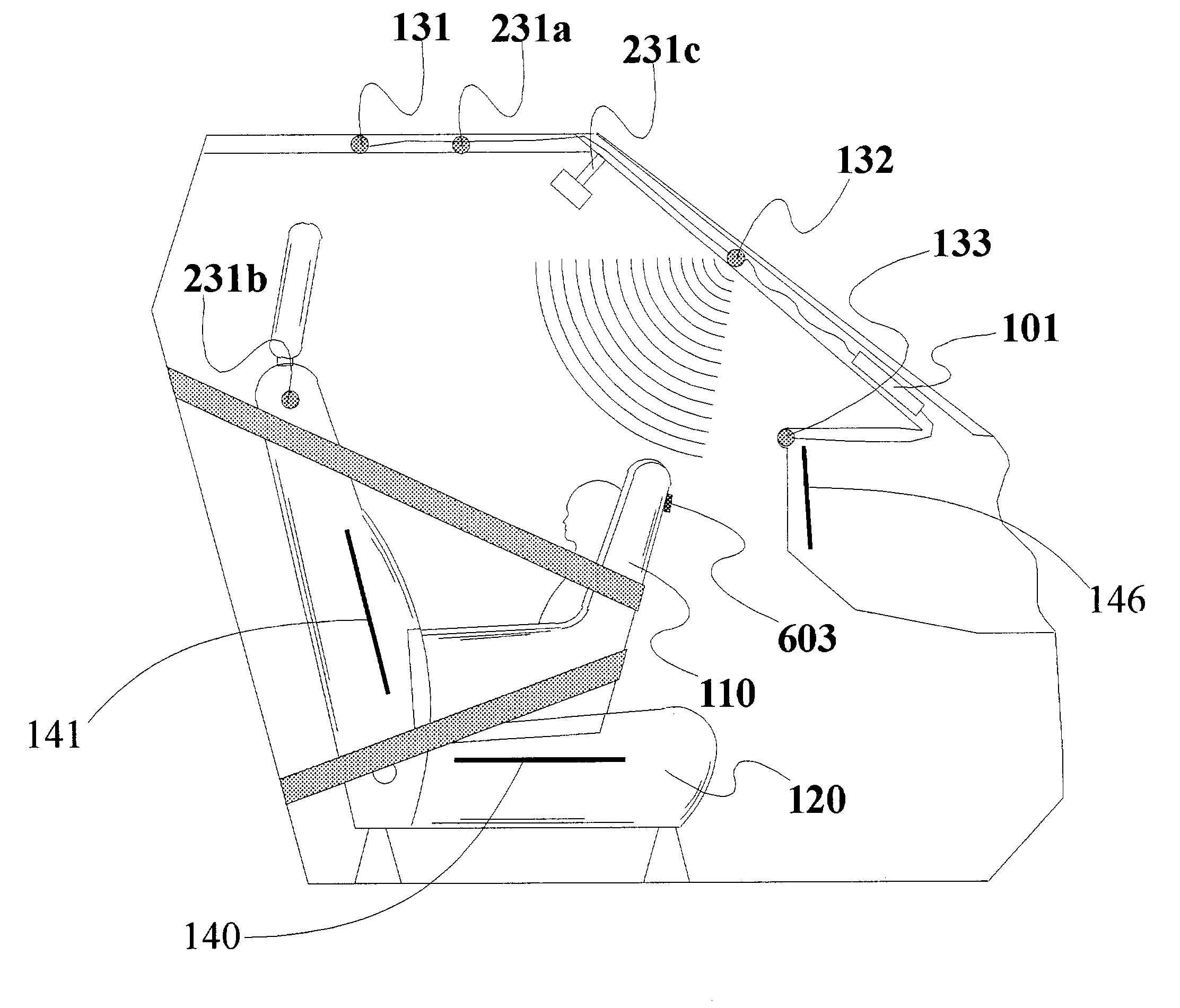
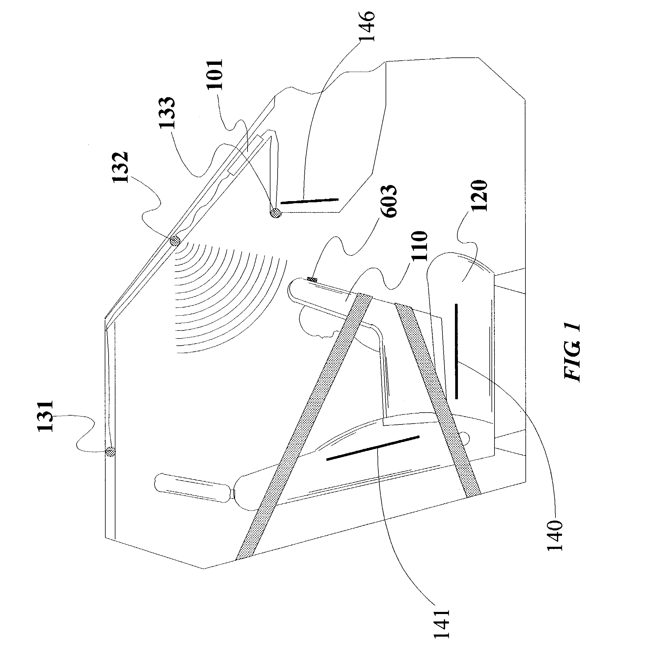
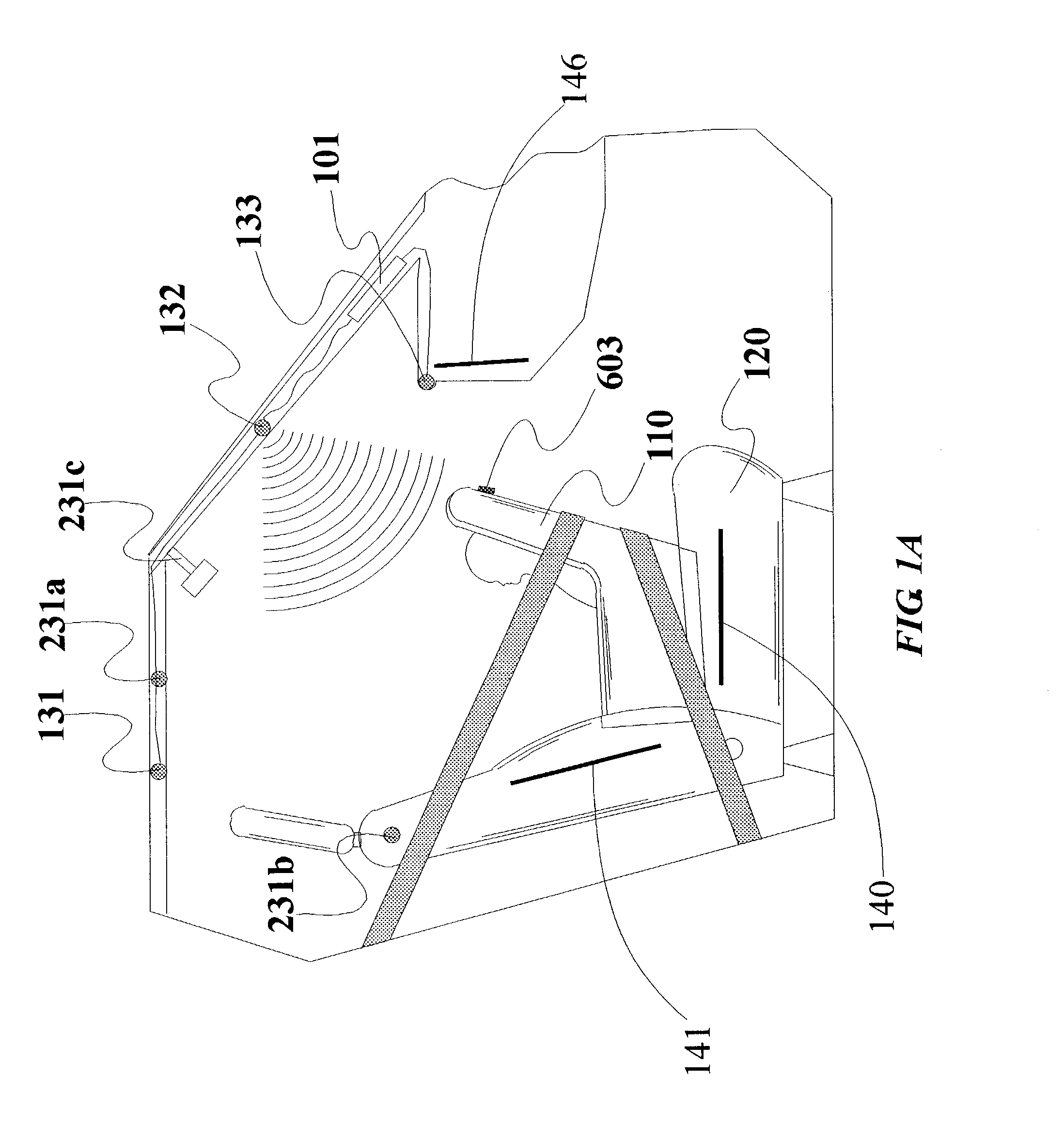
[0173]Referring to the accompanying drawings wherein the same reference numerals refer to the same or similar elements, FIG. 1 is a side view, with parts cutaway and removed of a vehicle showing the passenger compartment containing a rear facing child seat 110 on a front passenger seat 120 and a preferred mounting location for a first embodiment of a vehicle interior monitoring system in accordance with the invention. The interior monitoring system is capable of detecting the presence of an occupant and the rear facing child seat 110 (or more generally, a child seat and its orientation). In this embodiment, three transducers 131, 132 and 133 are used alone, or, alternately in combination with one or two antenna near field monitoring sensors or transducers, 140 and 141, although any number of wave-transmitting transducers or radiation-receiving receivers may be used. Such transducers or receivers may be of the type that emit or receive a continuous signal, a time varyi...


PUM


Abstract

A vehicle including a system for obtaining information about occupants of the vehicle including a rear-view mirror including a mirror part and a support for mounting the mirror part to the vehicle (such as to a windshield of the vehicle), a wave-receiving system arranged on the mirror for receiving waves from spaces above seats of the vehicle in which occupants would normally be situated and a processor coupled to the wave-receiving system and arranged to obtain information about the occupants based on the waves received by the wave-receiving system. The wave-receiving system may include an infrared receiver, a transmitter/receiver capable of transmitting and receiving waves, an ultrasonic wave receiver and/or an array for displaying infrared light reflected from or generated by the occupants. Based on the waves received by the wave-receiving system, the processor may identify or ascertain the identity of the occupants, determine the position or movement of the occupants and/or determine the distance between the wave-receiving system and the occupants. The processor may embody a pattern recognition system for obtaining information about the occupants based on training designed to create an algorithm capable of processing data on the waves received by the wave-receiving system into information about the occupants.

Description

CROSS REFERENCE TO RELATED APPLICATIONS[0001]This application is a continuation-in-part of U.S. patent application Ser. No. 10 / 114,533 filed Apr. 2, 2002 now U.S. Pat. No. 6,942,248 which in turn is a continuation-in-part of U.S. patent application Ser. No. 10 / 058,706 filed Jan. 28, 2002 which in turn is:[0002]1) a continuation-in-part of U.S. patent application Ser. No. 09 / 891,432, filed Jun. 26, 2001, now U.S. Pat. No. 6,513,833, which is a continuation-in-part of U.S. patent application Ser. No. 09 / 838,920 filed Apr. 20, 2001 now U.S. Pat. No. 6,778,672 which is a continuation-in-part of U.S. patent application Ser. No. 09 / 563,556 filed May 3, 2000, now U.S. Pat. No. 6,474,683, which is a continuation-in-part of U.S. patent application Ser. No. 09 / 437,535 filed Nov. 10, 1999 now U.S. Pat. No. 6,712,387 which in turn is a continuation-in-part of U.S. patent application Ser. No. 09 / 047,703 filed Mar. 25, 1998, now U.S. Pat. No. 6,039,139, which in turn is:[0003]a) a continuation-in...

Claims


Application Information

Patent Timeline
Patent Type & Authority Patents(United States)
IPC IPC(8): B60R21/16B60J10/00B60N2/00B60N2/02B60N2/28B60N2/48B60R1/12B60R16/02B60R16/037B60R21/01B60R21/013B60R21/0132B60R21/0134B60R21/015B60R21/20B60R21/215B60R21/231B60R21/26B60R21/276B60R22/20B60R22/48E05F15/00G01F23/00G01F23/20G01F23/296G01S7/41G01S7/48G01S7/539G01S13/04G01S15/04G01S15/06G01S15/87G01S15/88G01S17/88G01S17/89G06K9/00
CPCB60N2/4885B60R16/037B60R21/0136B60R22/20B60R25/25B60R25/252B60R25/255B60R25/257G01S7/417G01S7/4802G01S7/539G01S15/87G01S15/88G01S17/88G06K9/00362B60H1/00742B60J10/00B60N2/002B60N2/0232B60N2/0248B60N2/0276B60N2/28B60N2/2806B60N2/2863B60N2/4852B60R21/01554B60R21/01536B60R21/01516B60R21/01534B60R21/01538B60R21/01542B60R21/01552B60R21/0154E05F15/43E05F15/431E05F2015/433B60R21/0132B60R21/0134B60R21/21656B60R21/276B60R2001/1223B60R2001/1253B60R2021/0027B60R2021/01315B60R2021/23153B60R2021/26094B60R2021/2765B60R2022/208B60R2022/4825E05Y2400/664E05Y2400/85E05Y2900/55G01S13/04G01S15/04G01S15/06G01S17/89G10K2210/1282G10K2210/3219E05F15/00B60N2002/0272B60R21/01548B60R21/01544B60N2002/0268B60N2/888B60N2/853G06V40/10B60N2/02246B60N2/0272B60N2/0268B60R21/0153
Inventor BREED, DAVID S.DUVALL, WILBUR E.JOHNSON, WENDELL C.
Owner AMERICAN VEHICULAR SCI
Why Eureka
Try Eureka