Inflator

a technology of inflator and gas generating agent, which is applied in the direction of vehicle components, pedestrian/occupant safety arrangements, weapons, etc., can solve the problems that the inflator using pressurized gas and a gas generating agent together are attracting attention, and achieve the effect of convenient solidification

Inactive Publication Date: 2006-11-14
DAICEL CHEM IND LTD
View PDF43 Cites 21 Cited by
  • Summary
  • Abstract
  • Description
  • Claims
  • Application Information

AI Technical Summary

Benefits of technology

[0014]The above-described inventions are provided with the means for arresting the combustion residues contained in combustion gas of the gas generating agent respectively, the following advantageous effects (1) to (3) can be obtained.
[0015]By associating the discharging temperature of a gas generated from a gas generating agent and the melting point of a combustion residue contained in the combustion gas, generation of a massive (slag-like) combustion residue can be promoted. The temperature of the discharged gas of the gas generating agent can be obtained on the basis of a pressure inside the tank (an actually measured value) and a generated gas amount obtained at the time of being burnt in the tank having a predetermined volume and further the specific heat of the generated gas, for example, according to the following formula (values other than T2 in the formula can be obtained by calculations or the like). When the melting point of the residue becomes sufficiently higher than the temperature of the discharged gas (not less than 100° C., preferably not less than 500° C.), the combustion residue can be easily solidified and becomes massive (slag-like), and it remains inside the inflator to be suppressed from being discharged outside of the inflator.
[0017]In the formula, the meanings of symbols are as follows:
[0019]b term: calorie of discharged gas (gas discharged into the tank)
[0020]c term: calorie of mixed gaseous matter in the tank after actuation of the inflator (after mixed with initial air in the tank)

Problems solved by technology

However, with a development of an inflator for an inflating-type safety system for an automobile, an inflator using pressurized gas and a gas generating agent together is attracting attention.

Method used


Image

  • Inflator
  • Inflator
  • Inflator

Examples


embodiment 1

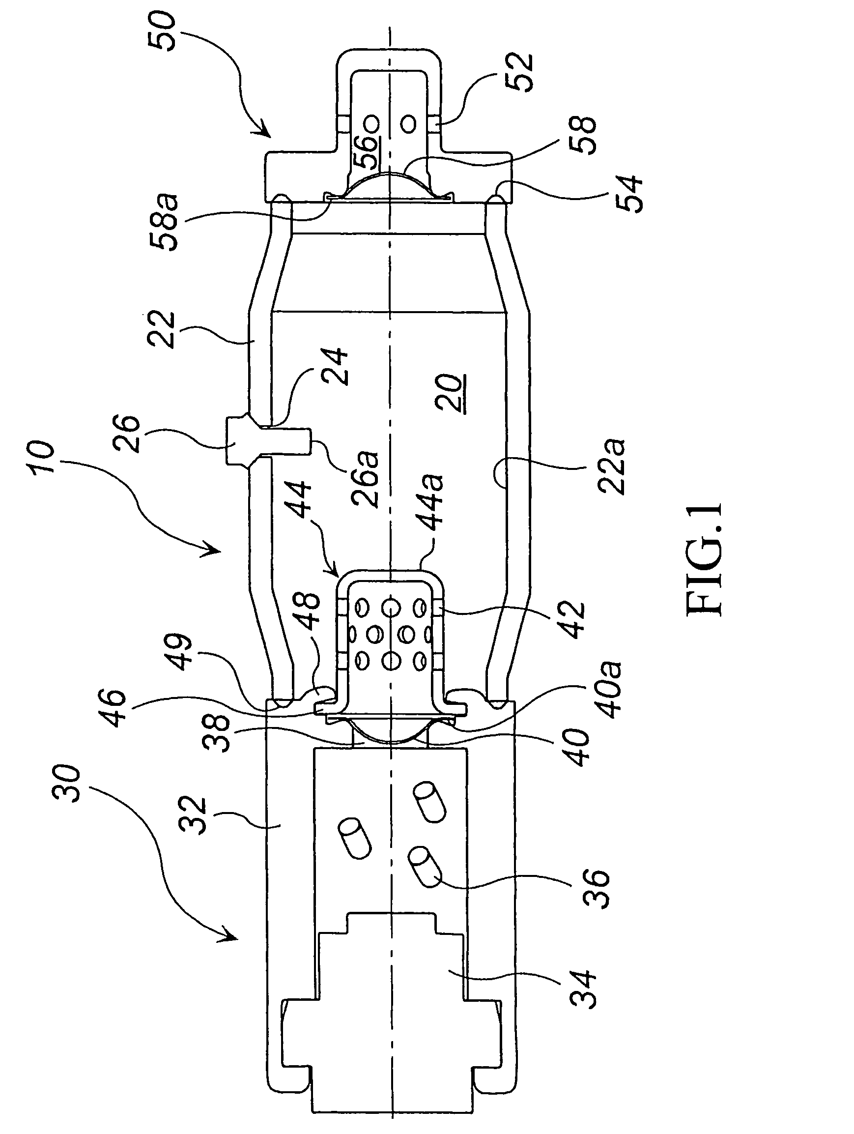
[0211]One embodiment will be explained with reference to FIG. 1. FIG. 1 is a sectional view of an inflator in the axial direction thereof.

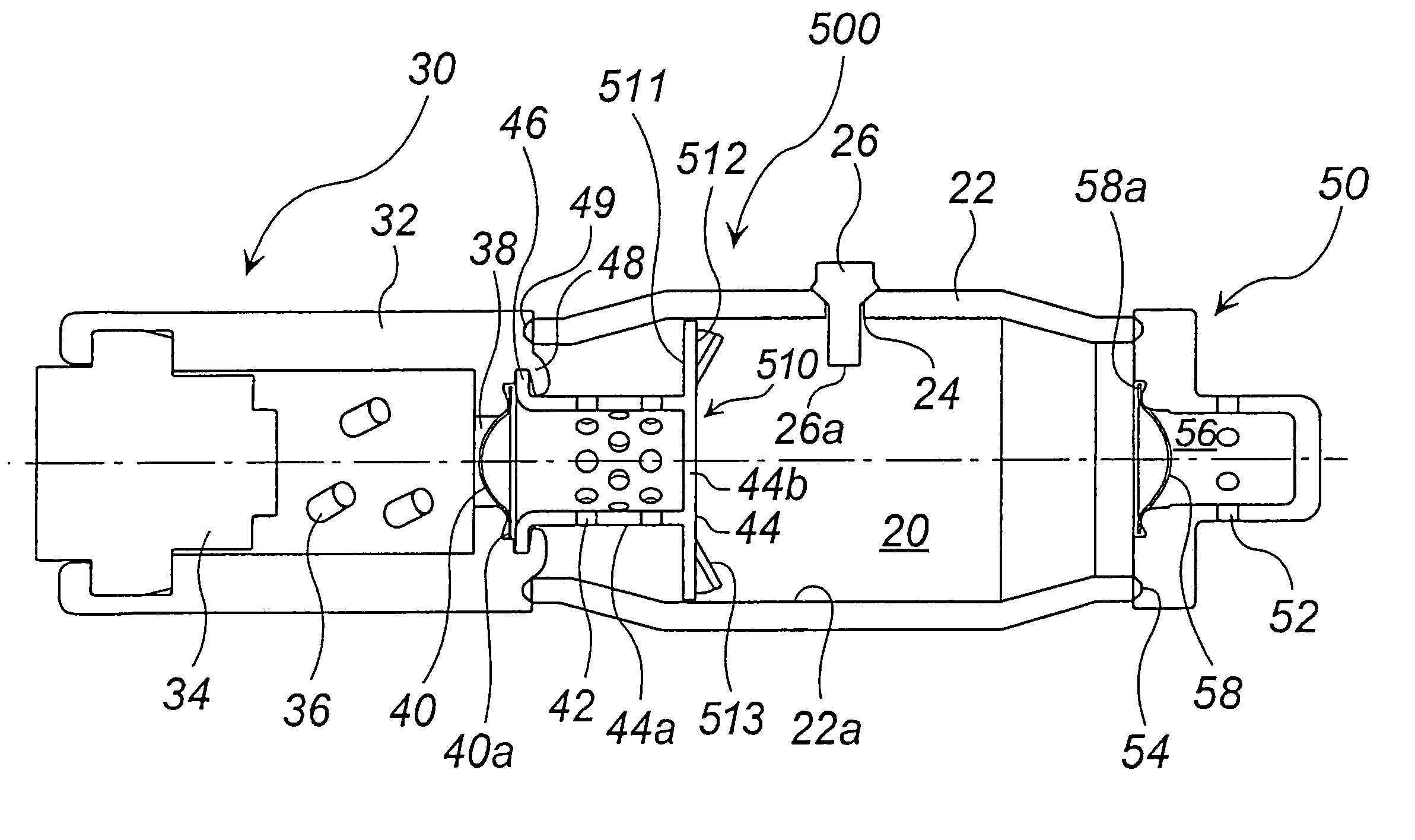
[0212]An inflator 10 comprises a pressurized medium chamber 20, a gas generator 30, and a diffuser portion 50.

[0213]The pressurized medium chamber 20 has an outer shell formed by a cylindrical pressurized medium chamber housing 22 and it is charged with a pressurized medium comprising a mixture of argon and helium. Since the pressurized medium chamber housing 22 is made symmetrical in the axial direction and a radial direction thereof, it is unnecessary to adjust the orientation in the axial and radial directions at a time of assembling.

[0214]A charging hole 24 of a pressurized medium is formed on a side surface of the pressurized medium chamber housing 22, and it is closed by a pin 26 after the pressurized medium is charged. A distal end portion 26a of the pin 26 protrudes into the pressurized medium chamber 20, and the protruding portion thereof...

embodiment 2

[0227]Another embodiment will be explained with reference to FIG. 3. FIG. 3 is a sectional view of an inflator in the axial direction thereof. An inflator 100 shown in FIG. 3 has almost the same structure as the inflator 10 shown in FIG. 1, and, in FIG. 3, the same reference numerals as those in FIG. 1 denote the same parts. A difference in structure from FIG. 1 and a difference in advantageous effect due to the difference in structure will be explained below.

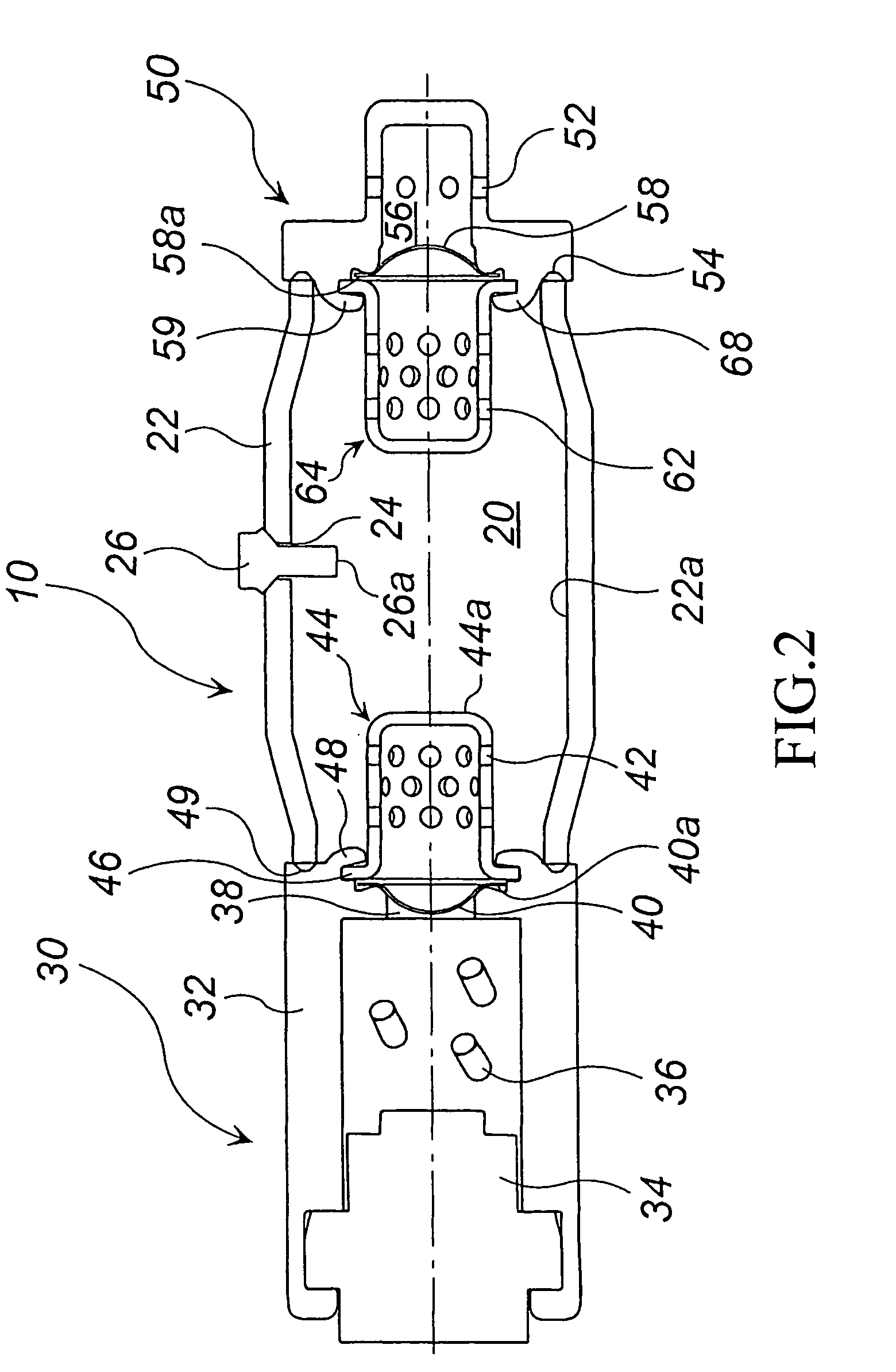
[0228]In the inflator 100 shown in FIG. 3, an inner wall surface 22a of a pressurized medium chamber housing 22 has one or more grooves with a depth of 0.2 mm formed continuously or discontinuously in the circumferential direction. By providing such grooves, a combustion residue contained in combustion gas is caught and captured in the groove, and the advantageous effect (4) can be exhibited in addition to the advantageous effects (1) to (3). Further, as shown in FIG. 2, an aspect in which a cap 64 is provided can be employed.

embodiment 3

[0229]Another embodiment will be explained with reference to FIG. 4. FIG. 4 is a sectional view of an inflator in the axial direction thereof. An inflator 200 shown in FIG. 4 has almost the same structure as that of the inflator 10 shown in FIG. 1, and, in FIG. 4, the same reference numerals as those in FIG. 1 denote the same parts. A difference in structure from FIG. 1 and a difference in advantageous effect due to the difference in structure will be explained below.

[0230]In an inflator 200 shown in FIG. 4, gas ejecting holes 42 are provided on a side wall 42a of the cap 44 and they are opened to eject combustion gas towards the gas generator 30. By providing such gas ejecting holes 42, combustion gas ejected from the gas ejecting holes 42 strikes against a crimped portion 48 and its vicinities before it strikes against the inner wall surface 22a of the pressurized medium chamber housing 22, and thereby, the advantageous effect (5) can be exhibited in addition to the advantageous e...


PUM

PropertyMeasurementUnit
distanceaaaaaaaaaa
diametersaaaaaaaaaa
areaaaaaaaaaaa

Abstract

Combustion residues of a gas generating agent remain in an inflator due to composition of the gas generating agent, temperature difference between combustion gas and pressurized gas isolated by a rupturable plate, collision of the combustion gas against a wall surface and the like. The inflator inflates an air bag with pressurized gas and combustion gas, while satisfying the following requirements: (1) pressurized gas contains an inert gas and substantially no oxygen; (2) in the gas generating agent, a pressure is 0.8 or less; (3) a mole ratio of an amount of pressurized gas and the combustion gas is 1 to 10; (4) a ratio of a mass of pressurized gas and the gas generating agent is 1 to 10; (5) a mass of a gas generating agent is 1 to 30 g; and (6) the pressurized gas is charged at 30,000 to 67,000 kPa.

Description

[0001]This application claims priority on provisional Application Nos. 60 / 359,989; 60 / 403,659; 60 / 409,267; and 60 / 411,085 filed on Feb. 28, 2002; Aug. 16, 2002; Sep. 10, 2002; and Sep. 17, 2002, respectively, and on Japanese Application Nos. 2001-367283; 2001-367536; 2002-234431; 2002-258010; 2002-264946; and 2002-323737, filed in Japan on Nov. 30, 2001; Nov. 30, 2001; Aug. 12, 2002; Sep. 3, 2002; Sep. 11, 2002; and Nov. 7, 2002, respectively, the entire contents of which are hereby incorporated by reference.BACKGROUND OF THE INVENTION[0002]1. Field of the Invention[0003]The present invention relates to an inflator suitable for an air bag system for an automobile. The present invention also provides an inflator in which pieces of a broken rupturable plate or combustion residues of a gas generating agent are prevented from flowing out of the inflator.[0004]2. Description of the Related Art[0005]As an inflator used in an air bag system for an automobile, there is a type in which an ai...

Claims


Application Information

Patent Timeline
Patent Type & Authority Patents(United States)
IPC IPC(8): B60R21/26B60R21/264B60R21/272C06D5/06
CPCB60R21/261B60R21/272C06D5/06B60R2021/2633B60R2021/2648
Inventor MATSUDA, NAOKIIWAI, YASUNORIKATSUDA, NOBUYUKI
Owner DAICEL CHEM IND LTD
Why Eureka
Try Eureka