Bumper for reducing pedestrian injury

a technology for pedestrians and bumpers, applied in the direction of bumpers, vehicle components, pedestrian/occupant safety arrangements, etc., can solve the problems of difficult to reduce the magnitude and rate of energy transfer from bumpers to pedestrians upon impact, human body cannot withstand high-energy impacts nor sharp impacts without substantial damage to muscle and bone tissue, etc., to achieve less injury, less energy, and reduce injury

Inactive Publication Date: 2006-11-14
SHAPE CORP
View PDF28 Cites 35 Cited by
  • Summary
  • Abstract
  • Description
  • Claims
  • Application Information

AI Technical Summary

Benefits of technology

[0005]In one aspect of the present invention, a bumper system for a vehicle includes a beam adapted for attachment to a vehicle, and an energy absorber engaging a face of the beam. The energy absorber has a top horizontal section defined by a top wall and an upper-mid wall connected by an upper-front wall, and also has a bottom horizontal section defined by a bottom wall and a lower-mid wall connected by a lower-front wall, and still further has a middle horizontal section defined by a mid-front wall connecting the upper-mid wall and the lower-mid wall. The top and bottom horizontal sections include top and bottom front nose portions that extend forward of the mid-front wall and that define a horizontal channel therebetween in front of the mid-front wall. The front nose portions are configured to provide a first level of energy absorption during an initial impact stroke that collapses one or both of the front nose portions, with the top, middle, and bottom horizontal sections providing a higher second level of energy absorption during a continuing impact stroke that collapses the energy absorber against the face of the beam. A fascia covers the energy absorber and the beam. By this arrangement, during an initial front impact stroke, the top and bottom front nose portions provide a relatively low-energy absorption that “catches” an impacted object such as a knee of a human being, and then during a further continuing impact stroke, the top, middle, and bottom horizontal sections crush to provide an increased energy absorption.
[0008]The objects of the present invention include providing a bumper system adapted to initially “catch” a person during an initial phase of impact, with less energy and forces being transmitted to the person and / or the forces being transmitted at a slower rate during the initial phase, and hence less injury being likely. The objects further include re-orienting the impact forces transmitted to the person from a line parallel the direction of impact to a direction upward or downward (in the case of a front impact) or laterally (in the case of a corner impact). By these actions, the impacted person is initially “caught” and then “thrown” in a direction away from the line of impact, thus reducing injury and also reducing damage to the vehicle bumper system.

Problems solved by technology

However, design of bumpers for pedestrian safety is complicated by several conflicting functional requirements.
Obviously, the human body cannot withstand high-energy impacts nor sharp impacts without substantial damage to muscle and bone tissue.
However, it is difficult to reduce the magnitude and rate of energy transfer from a bumper to a pedestrian upon impact, especially immediate transfer of energy from a “sharp” impact, because vehicle bumpers are usually limited to a relatively short stroke by components behind the bumper, such as a radiator and other engine components, and also limited by other front-end components and supporting structure.
The problems are further complicated by aerodynamic designs, where corners of the bumper system are swept and curved back into the vehicle fenders, which further limits bumpers strokes and the bumper's ability to collapse or flex.
Also, the problem is compounded by the fact that bumpers are at knee-height, such that pedestrian-related vehicular accidents often involve trauma to the pedestrian's knees.
Joints and exposed bones are particularly prone to injury upon impact.

Method used


Image

  • Bumper for reducing pedestrian injury
  • Bumper for reducing pedestrian injury
  • Bumper for reducing pedestrian injury

Examples


Embodiment Construction

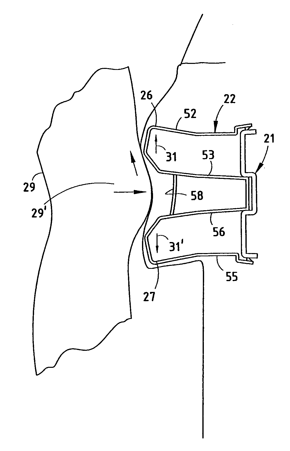
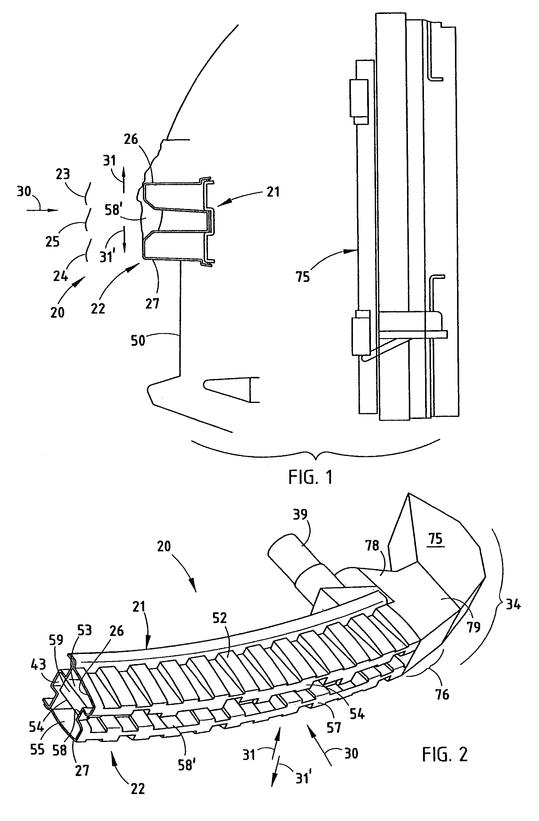
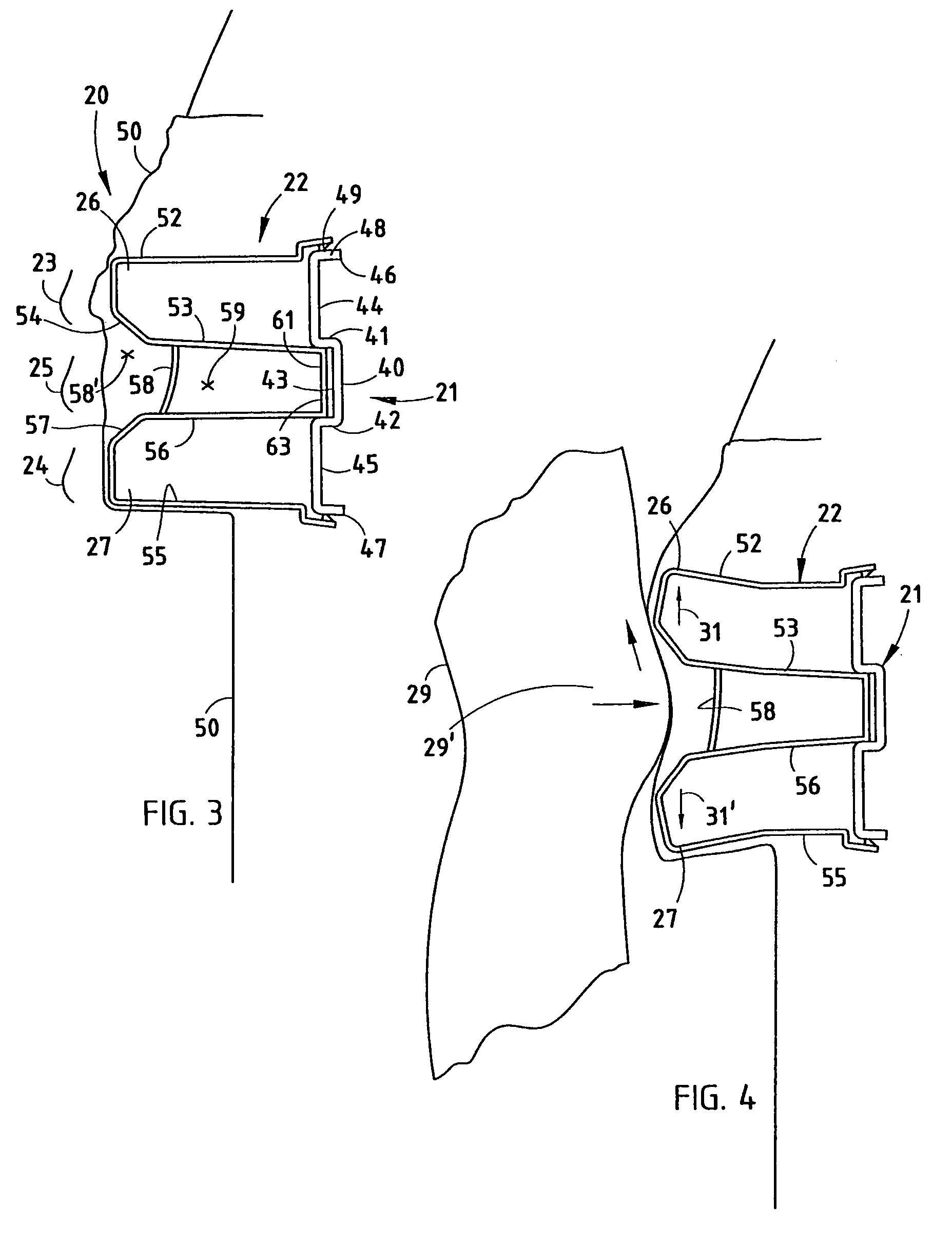
[0018]A vehicle bumper system 20 (FIGS. 1–2) includes a beam 21, and an energy absorber 22 with top and bottom horizontal sections 23, 24, and a middle horizontal section 25. The top and bottom horizontal sections 23–24 form top and bottom nose portions 26 and 27 that are semi-rigid but collapsible with a parallelogram motion that shifts the top and bottom portions 26 and 27 vertically up (or down) upon impact. As a result, horizontal impact forces 30 are converted in part to vertical forces 31 during an initial stroke of a frontal impact (FIG. 4), in effect “catching” the knee 29′ (FIG. 4) of a human 29 during a collision. Upon a continuing impact stroke (FIG. 5), the top and bottom horizontal sections 23–24 provide a “throwing” action, as shown by increasing forces 31 and 31′. During the continuing impact stroke, the horizontal sections 23–25 also crush and provide increased energy absorption, as shown by FIG. 5. The combination of these forces 31 and 31′“throw” the impacted human...


PUM


Abstract

A vehicle bumper system includes a beam, and an energy absorber with top and bottom horizontal sections and a mid-horizontal section. The horizontal sections form top and bottom nose portions that are semi-rigid but initially collapsible with a parallelogram motion that shifts the top and bottom portions vertically up (or down) upon-impact. Horizontal impact forces are converted in part to vertical forces during an initial stroke of a frontal impact, “catching” an impacted human being. Then during a further continuing impact stroke, the top and bottom horizontal sections provide a “throwing” action. End sections of the energy absorber extend around ends of a bumper beam, forming a collapsible corner that, during impact, initially absorbs energy at a low rate to “catch” a person, and then develops increasing lateral forces that “throw” the person during a continuing impact stroke.

Description

CROSS-REFERENCE TO RELATED APPLICATION[0001]This application is a continuation of U.S. patent application Ser. No. 10 / 208,300 filed on Jul. 30, 2002 entitled BUMPER FOR REDUCING PEDESTRIAN INJURY, now U.S. Pat. No. 6,685,243.BACKGROUND[0002]The present invention relates to bumpers for passenger vehicles designed to reduce pedestrian injury upon impact, and more particularly relates to a bumper having an energy absorber optimized to provide a relatively soft initial impact and a “throwing” force after initial impact to a pedestrian struck by the bumper.[0003]Automotive bumper systems in the United States have been designed for resistance to damage at low and high vehicle speeds and for high-energy absorption at high impact speeds. Recently, pedestrian safety has begun to receive increasing attention. However, design of bumpers for pedestrian safety is complicated by several conflicting functional requirements. Obviously, the human body cannot withstand high-energy impacts nor sharp i...

Claims


Application Information

Patent Timeline
Patent Type & Authority Patents(United States)
IPC IPC(8): B60R19/18
CPCB60R19/18B60R21/34B60R19/26B60R2019/1806B60R2019/1866B60R2019/188B60R2019/247B60R2021/0009B60R2021/343
Inventor EVANS, DARIN
Owner SHAPE CORP
Why Eureka
Try Eureka