Precast concrete slab system and method therefor

a prefabricated concrete and slab technology, applied in the field of prefabricated concrete slabs, can solve the problems of inability of the slab to provide for tension in two dimensions, settle and crack, and inability to provide continuous tensile forces, and achieve the effect of quick and easy fitting

Inactive Publication Date: 2006-11-14
ELIZABETH WONG YEE TRUSTEE OF THE ELIZABETH YEE REVOCABLE LIVING TRUST UNDER AGREEMENT DATED NOVEMBER 11 1981 AS AMENDED & RESTATED +1
View PDF19 Cites 61 Cited by
  • Summary
  • Abstract
  • Description
  • Claims
  • Application Information

AI Technical Summary

Benefits of technology

[0007]The present invention comprises a plurality of male type prefabricated concrete slabs and female type prefabricated concrete slabs which can be quickly and easily fitted to each other in a checkerboard fashion for repair to roadways, airplane runways and other applications where concrete slabs can be typically used. The prefabricated male and female slabs are each individually reinforced by metal rods which extend therethrough in both longitudinal and transverse directions and are interconnected along each side by a plurality of male and female connectors, which serve to reinforce the assembled slab system continuously in both the longitudinal and transverse directions.
[0010]The female socket fixtures at corresponding positions on opposite sides of the female slab are interconnected by at least one steel reinforcing rod, and preferably two, that extend the length and width of the female slab in both the longitudinal (X) direction and transverse (Y) direction. When the male and female slabs are assembled, with the male connectors properly positioned within their corresponding female connector sockets, the female sockets are then filled with high strength grout or other solidifying material to finish off the connection. When so assembled, the longitudinal and transverse reinforcing rods in conjunction with the male and female connectors provide continuous reinforcement between the male and female slabs in two directions, both longitudinally and transversely.
[0012]In a preferred embodiment of the present invention, the head or similar fixture fitted to the distal end of the metal rods projecting from the sides of the male slab is in the form of a large threaded nut which is threadedly engaged upon threads formed at the distal end of the metal rods. This threaded engagement between the nuts and distal ends allows for minor adjustment of the male connectors in the longitudinal direction so as to compensate for minor variations in the male connectors and the female sockets.
[0016]Accordingly, it is an object of the present invention to provide a precast concrete slab connector system that allows two adjacent preformed concrete slabs to be connected together quickly and easily.
[0020]It is a still further object of the present invention to provide a precast concrete slab system wherein female type pre-fabricated concrete slabs have a plurality of connector sockets which are designed to allow the projecting male connectors to drop into the female connector sockets on one to four sides when a male slab is lowered and fitted adjacent one or more female slabs. The socket fixtures in the female slabs are connected to steel reinforcing rods that extend the length and width of the slab in the longitudinal and transverse directions to provide superior strength and develop full tension reinforcement between the male and female slabs in two dimensions.
[0022]Yet another object of this invention to be specifically enumerated herein is to provide a precast concrete slab system in accordance with the preceding objects which will conform to conventional forms of manufacture, be of simple construction and easy to use so as to provide a precast concrete slab system that will be economically feasible, strong and long lasting and relatively trouble free in installation and use.

Problems solved by technology

Concrete structures are known to wear, deteriorate, settle and crack over time with continuous use as well as to exposure to traffic, weather and extremes of temperature.
One of the problems with the prior art concrete slabs is the inability of the slabs to provide for tension in two dimensions.
(1,991,931) the slabs have interlocking tabs but they do not provide for continuous tensile forces between the precast panels, nor do they provide sufficient shear resistance between panels.
However, the Ruckstuhl structure lacks simplicity.
The connection hardware consists of a plate and screws which are inset into the precast slab, and the system uses highly precisioned complex metal parts that allow little tolerance and are impractical in the field.
A similar problem is found with the structure of the Tolliver et al.
This must be the case for every single connecting bolt, and in concrete construction in the field, this is practically impossible.
From a practical use standpoint, this is not ordinarily possible on a real road situation, certainly not one that seeks repair in a matter of hours.
The structure of the Smith patent (U.S. Pat. No. 6,607,327) does evidence some tensile strength in two dimensions, however, it is relatively weak and does not realize the benefit of using continuous tensile steel to anchor the connectors in two dimensions.

Method used


Image

  • Precast concrete slab system and method therefor
  • Precast concrete slab system and method therefor
  • Precast concrete slab system and method therefor

Examples


Embodiment Construction

[0041]Although preferred embodiments of the present invention are explained in detail, it is to be understood that other embodiments are possible. Accordingly, it is not intended that the invention is to be limited in its scope to the details of constructions and arrangement of components set forth in the following description or illustrated in the drawings. The invention is capable of other embodiments and of being practiced or carried out in various ways. Also, in describing the preferred embodiments, specific terminology will be resorted to for the sake of clarity. It is to be understood that each specific term includes all technical equivalents which operate in a similar manner to accomplish a similar purpose. Further, although the drawings are intended to illustrate the present invention, the drawings are not necessarily drawn to scale.

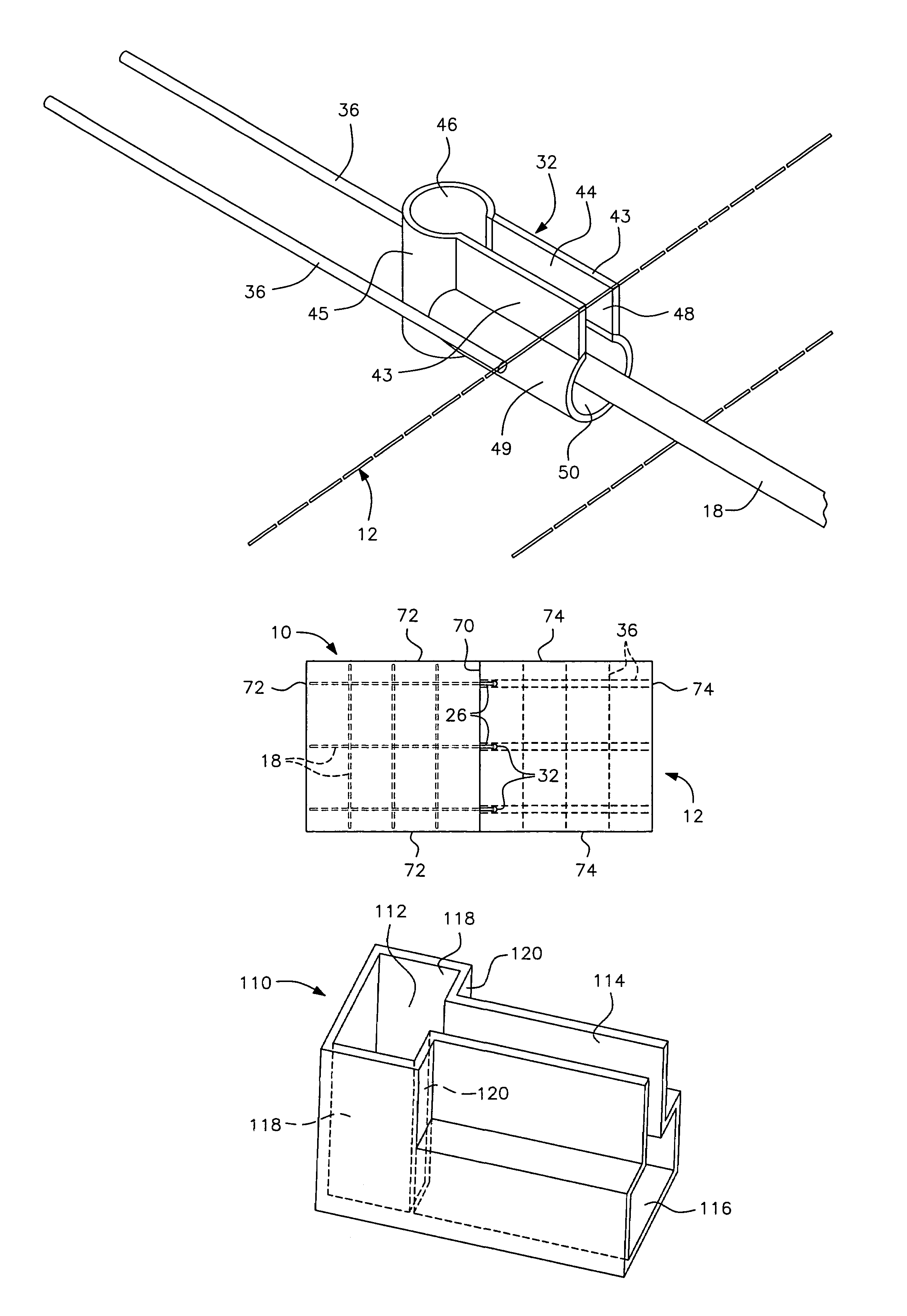
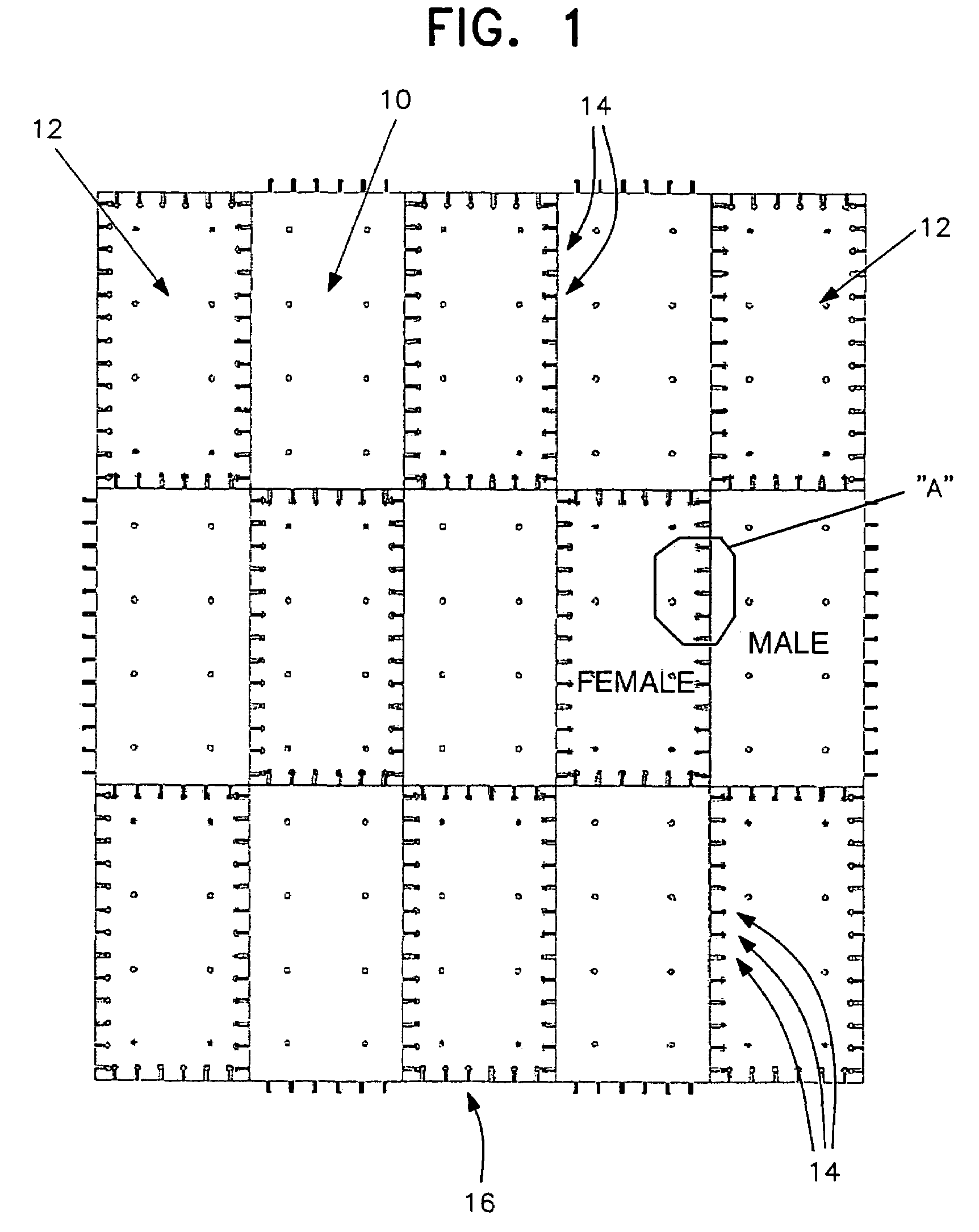
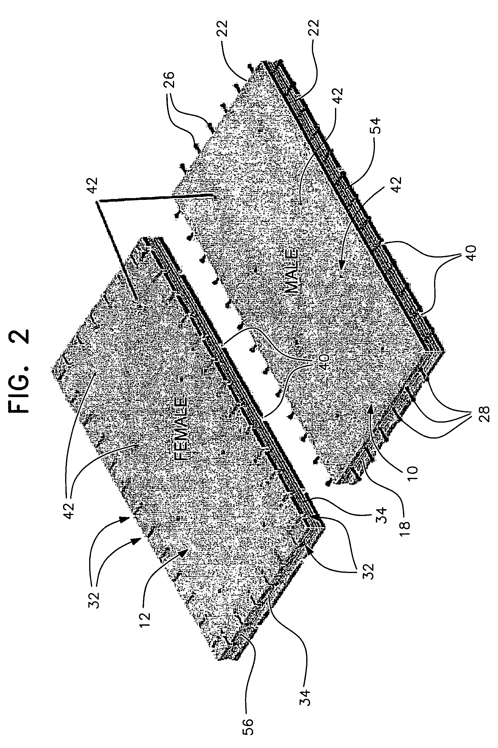
[0042]Referring to the drawings, FIG. 1 shows a plan view of rectangular male slabs, generally designated by reference numeral 10, and similarly...


PUM


Abstract

A pre-fabricated concrete slab system and method have matching rectangular male and female type slabs which fit adjacent to each other in a checkerboard fashion. The male slabs include spaced reinforcing rods extending longitudinally and transversely through the male slabs with the rods' distal ends protruding outwardly away from one or more side edges of the male slabs to form a plurality of male connectors. The female slabs include a plurality of corresponding female sockets on one or more sides of the female slab, each female socket receiving a corresponding male connector when dropped therein. Corresponding female sockets positioned on opposite side edges of the female slabs are interconnected by steel reinforcing bars in both the longitudinal and transverse directions in a configuration similar to the male slabs so that, when connected, a continuous tension reinforcement is established between male and female slabs in both the longitudinal and transverse directions.

Description

FIELD OF INVENTION[0001]The present invention relates generally to pre-fabricated concrete slabs or other forms that can be rapidly connected and used for repairs on highway pavements, roadways and parking lots, bridge decks, aircraft runways, taxiways, buildings, floors, roofs, or any structure made using precast concrete forms. More specifically, the present invention is directed to an interlocking system that allows the precast slabs or forms to be quickly and easily set tightly joined together, while maintaining continuous tension reinforcement in two dimensions and with a minimum of grouting and alignment.INTRODUCTION[0002]Concrete structures are known to wear, deteriorate, settle and crack over time with continuous use as well as to exposure to traffic, weather and extremes of temperature. A good example of this type of structure is a concrete roadway. One of the faster methods of repairing concrete roadways is through the use of precast concrete slabs. The damaged area of pav...

Claims


Application Information

Patent Timeline
Patent Type & Authority Patents(United States)
IPC IPC(8): E01C11/04E01C5/00E01C5/08E01C5/10E04B1/04E04B1/41E04B1/48E04B5/02F16L9/08F16L13/11
CPCF16L13/113E01C5/08E01C5/10E04B1/4114E04B1/48E04B5/04F16L9/085E04B1/043E01C2201/12E01C2201/167Y10T403/7094E04B1/483E04B5/023F16B2200/30
Inventor YEE, ALFRED A.
Owner ELIZABETH WONG YEE TRUSTEE OF THE ELIZABETH YEE REVOCABLE LIVING TRUST UNDER AGREEMENT DATED NOVEMBER 11 1981 AS AMENDED & RESTATED
Why Eureka
Try Eureka