In-mold radio frequency identification device label

a radio frequency identification and label technology, applied in the field of labels, can solve the problems of poor solution of simple adhesion of radio frequency identification device labels to these items, and achieve the effect of improving bonding and structural integrity

Inactive Publication Date: 2006-11-14
BRADY WORLDWIDE INC
View PDF27 Cites 38 Cited by
  • Summary
  • Abstract
  • Description
  • Claims
  • Application Information

AI Technical Summary

Benefits of technology

[0015]It is therefore an advantage of the present invention to provide a label including a radio frequency identification device wherein the label protects the radio frequency identification device chip during and after in-molding of the label in an article.
[0016]It is another advantage of the present invention to provide a label including a radio frequency identification device wherein the label includes a protective outer sheet that resists mechanical and chemical damage.
[0017]It is yet another advantage of the present invention to provide a label including a radio frequency identification device wherein the label provides for improved structural integrity during an in-molding process.
[0018]It is still another advantage of the present invention to provide a label including a radio frequency identification device wherein the label allows for improved bonding to an article during an in-molding process.
[0019]These and other features, aspects, and advantages of the present invention will become better understood upon consideration of the following detailed description, drawings, and appended claims.

Problems solved by technology

Simple adhesion of a radio frequency identification device label to these items is a poor solution, because the label would be rendered inoperative from normal long-term wear.

Method used


Image

  • In-mold radio frequency identification device label
  • In-mold radio frequency identification device label

Examples


example 1

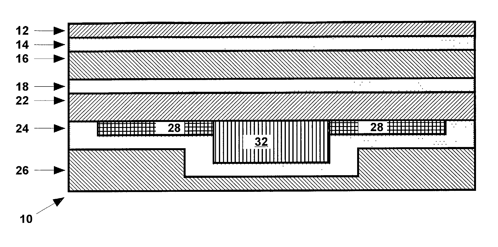
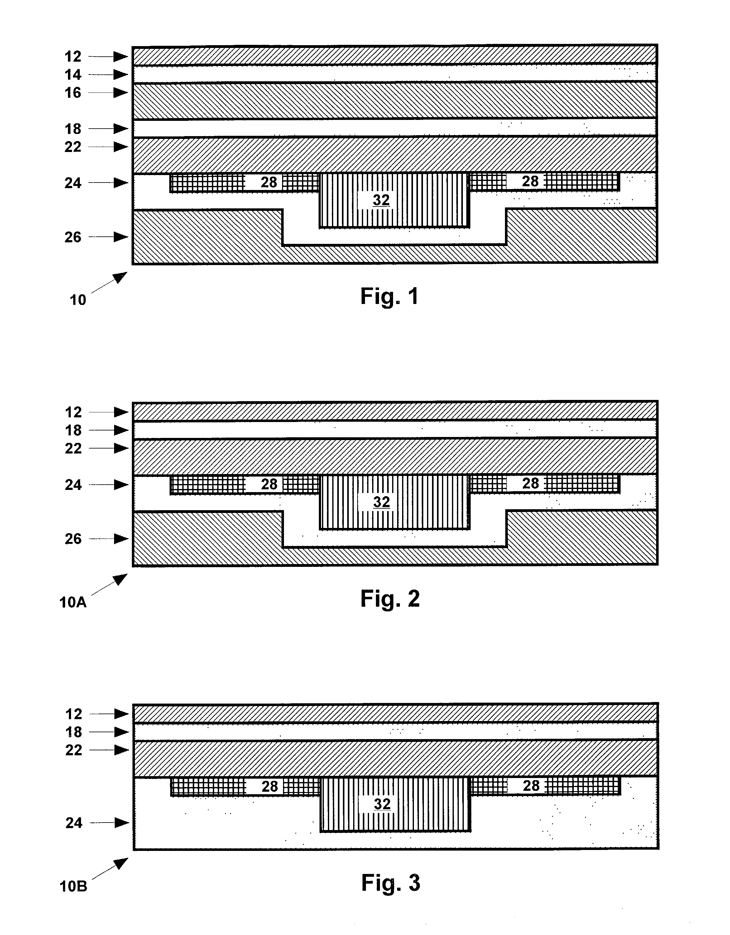
[0039]A label 10 as shown in FIG. 1 was prepared as follows. The label 10 was made by: (1) solvent coating, at about 2 to 6# / ream, two 0.0070″ thick polyolefin films (Teslin® brand porous silica filled polyethylene available from PPG Industries) with a thermoplastic heat activated adhesive polyester resin (MorEster® 49000 brand polyester resin available from Rohm and Haas); (2) heat laminating a flexible radio frequency identification device to the polyolefin layers at 275° F. at a speed that is slow enough to soften the polyolefin so it can form around the irregular profile of the integrated circuit chip and antenna of the radio frequency identification device; and (3) heat laminating a 0.001″ polyester film with a polyethylene heat laminating adhesive to the flat side (non-chip side) of the polyolefin-radio frequency identification device laminate. The end product can be supplied in either continuous rolls, scored or perforated rolls, or individual cut tags.

[0040]Fifty labels were...

example 2

[0041]A label 10A as shown in FIG. 2 was prepared as follows. The label 10A was made by: (1) solvent coating, at about 2 to 6# / ream, a 0.002″ thick white pigmented polyester film (e.g., Mylar® brand pigmented polyester film available from DuPont) and a 0.0070″ thick polyolefin film (Teslin® brand porous silica filled polyethylene available from PPG Industries) with a thermoplastic heat activated adhesive polyester resin (Mor-Ester® 49000 brand polyester resin available from Rohm and Haas); (2) heat laminating the chip side of a radio frequency identification device to the polyolefin layer at 275° F. at a speed that is slow enough to soften the polyolefin so it can form around the irregular profile of the integrated circuit chip and antenna of the radio frequency identification device; and (3) heat laminating the polyester film to the flat side (non-chip side) of the polyolefin-radio frequency identification device laminate. The end product can be supplied in either continuous rolls,...


PUM

PropertyMeasurementUnit
thicknessaaaaaaaaaa
thicknessaaaaaaaaaa
thicknessaaaaaaaaaa

Abstract

A label for use as an in-mold label and including a radio frequency identification device (RFID) is disclosed. The label includes an RFID having opposed first and second surfaces; a first layer of heat-activated adhesive disposed on the first surface of the RFID; a second layer of heat-activated adhesive disposed on the second surface of the RFID; and a surface layer comprising a polymeric film disposed on a surface of the first layer of heat-activated adhesive opposite the first surface of the RFID. The label is placed in a mold with the surface layer contacting the mold. A polymer is molded in the mold such that the second layer of heat-activated adhesive (or a surface layer over the second layer of heat-activated adhesive) adheres to the polymer thereby producing a labeled article that can be identified using the radio frequency identification device in the label.

Description

CROSS-REFERENCES TO RELATED APPLICATIONS[0001]Not Applicable.STATEMENT REGARDING FEDERALLY SPONSORED RESEARCH[0002]Not Applicable.BACKGROUND OF THE INVENTION[0003]1. Field of the Invention[0004]This invention relates to labels including a radio frequency identification device, and more particularly to labels including a radio frequency identification device wherein the label is compatible with an in-mold process. This allows the label to be incorporated into plastic parts, such as bins and pallets, for durable tracking purposes.[0005]2. Description of the Related Art[0006]It is well known that items, such as plastic bins and pallets in a factory, can be tracked and identified using a radio frequency identification device (RFID). An RFID generally includes an antenna connected to an integrated circuit chip in which digital information is stored. The RFID transmits stored data by reflecting varying amounts of an electromagnetic field provided by an RFID interrogator. An RFID can now b...

Claims


Application Information

Patent Timeline
Patent Type & Authority Patents(United States)
IPC IPC(8): G08B13/14G06K19/077
CPCG06K19/07749Y10T428/2848
Inventor SAVAGIAN, MICHAEL D.MESS, STEVEN H.
Owner BRADY WORLDWIDE INC
Why Eureka
Try Eureka