Image processing method and apparatus, control method therefor, and storage medium

a technology of image processing and control method, applied in the direction of color television details, television system details, television systems, etc., can solve the problems of limited image sensing purpose, and inability to provide convenient image processing apparatus, etc., to achieve smooth control of image processing apparatus

Inactive Publication Date: 2006-11-14
CANON KK
View PDF12 Cites 85 Cited by
  • Summary
  • Abstract
  • Description
  • Claims
  • Application Information

AI Technical Summary

Benefits of technology

[0015]It is another object of the present invention to provide a storage medium storing a control program that can smoothly control the image processing apparatus of the present invention.
[0016]It is still another object of the present invention to provide an image processing apparatus which does not pose any problem in panoramic image sensing

Problems solved by technology

However, in such conventional image processing apparatus such as an electronic camera or the like, since it is hard to sense a panoramic image with a complicated combination of images or to provide a viewfinder display which is convenient upon sensing a panoramic image with a complicated combination of images, its image sensing purpose is limited.
When the user of the image processing apparatus such as an electronic camera or the like has determined the camera angle, since he or she cannot start panoramic image sensing in an arbitrary direction, a convenient image processing apparatus cannot be provided.
Furthermore, since neither viewfinder display nor operation that facilitate re-sensing are available immediately after sensing of a panoramic image, a convenient image processing apparatus cannot be provided.
In such case, upon generating a panoramic image by combining a plurality of sensed images, extra computations for correcting different focal lengths are needed,

Method used


Image

  • Image processing method and apparatus, control method therefor, and storage medium
  • Image processing method and apparatus, control method therefor, and storage medium
  • Image processing method and apparatus, control method therefor, and storage medium

Examples


first embodiment

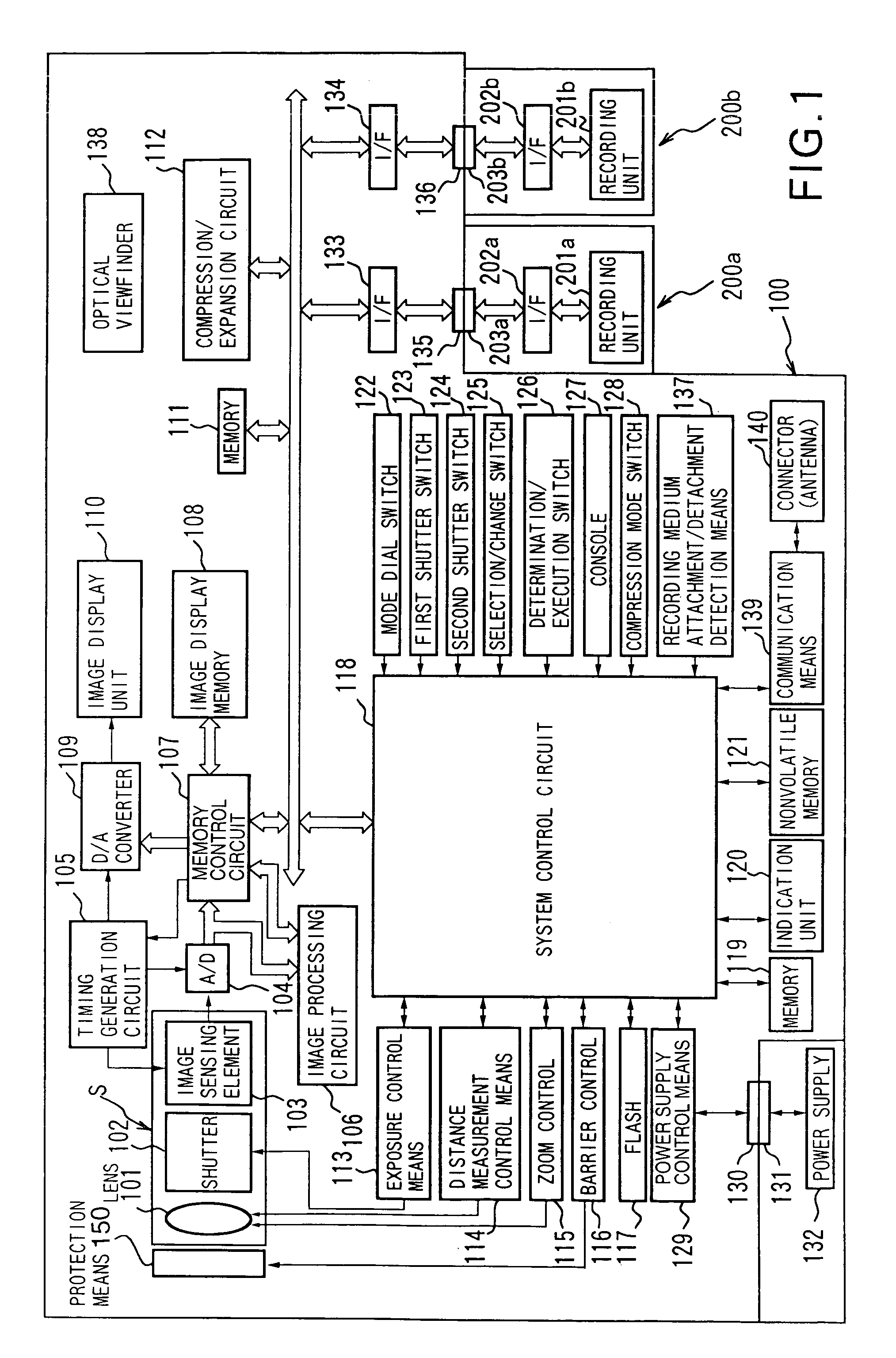
[0164]FIG. 1 is a block diagram showing the arrangement of an image processing apparatus according to the first embodiment. Referring to FIG. 1, reference numeral 100 denotes an image processing apparatus; and 101, a photographing lens used for sensing an object image. Reference numeral 102 denotes a shutter with a stop function. Reference numeral 103 denotes an image sensing element for converting an optical image into an electrical signal. Reference numeral 104 denotes an A / D converter for converting an analog signal output from the image sensing element 103 into a digital signal. Reference numeral 105 denotes a timing generation circuit for supplying clock signals and control signals to the image sensing element 103, the A / D converter 104, and a D / A converter 109 (to be described later). The timing generation circuit 105 is controlled by a memory control circuit 107 and system control circuit 118 (to be described later).

[0165]Reference numeral 106 denotes an image processing circ...

second embodiment

[0294]FIG. 16 shows the arrangement of an image processing apparatus according to the second embodiment of the present invention.

[0295]Referring to FIG. 16, reference numeral 400 denotes an image processing apparatus.

[0296]Reference numeral 14 denotes an image sensing element for converting an optical image into an electrical signal; and 16, an A / D converter for converting an analog signal output from the image sensing element 14 into a digital signal.

[0297]Reference numeral 18 denotes a timing generation circuit for supplying clock signals and control signals to the image sensing element 14, the A / D converter 16, and a D / A converter 26. The timing generation circuit 18 is controlled by a memory control circuit 22 and system control circuit 50.

[0298]Reference numeral 20 denotes an image processing circuit which performs predetermined pixel interpolation and color conversion for data supplied from the A / D converter 16 or the memory control circuit 22.

[0299]The image processing circui...

third embodiment

[0477]The operation of the third embodiment will be described below with reference to FIGS. 22, 23, 24, 25, 26, 5, 6, 7, and 8. The arrangement of the third embodiment has the same appearance as that of the second embodiment, except for its operation. Also, the processes shown in FIGS. 5, 6, 7, and 8 are the same as those in the second embodiment, and a detailed description thereof will be omitted.

[0478]The operation of the third embodiment will be explained below using FIGS. 22, 23, 24, 25, and 26.

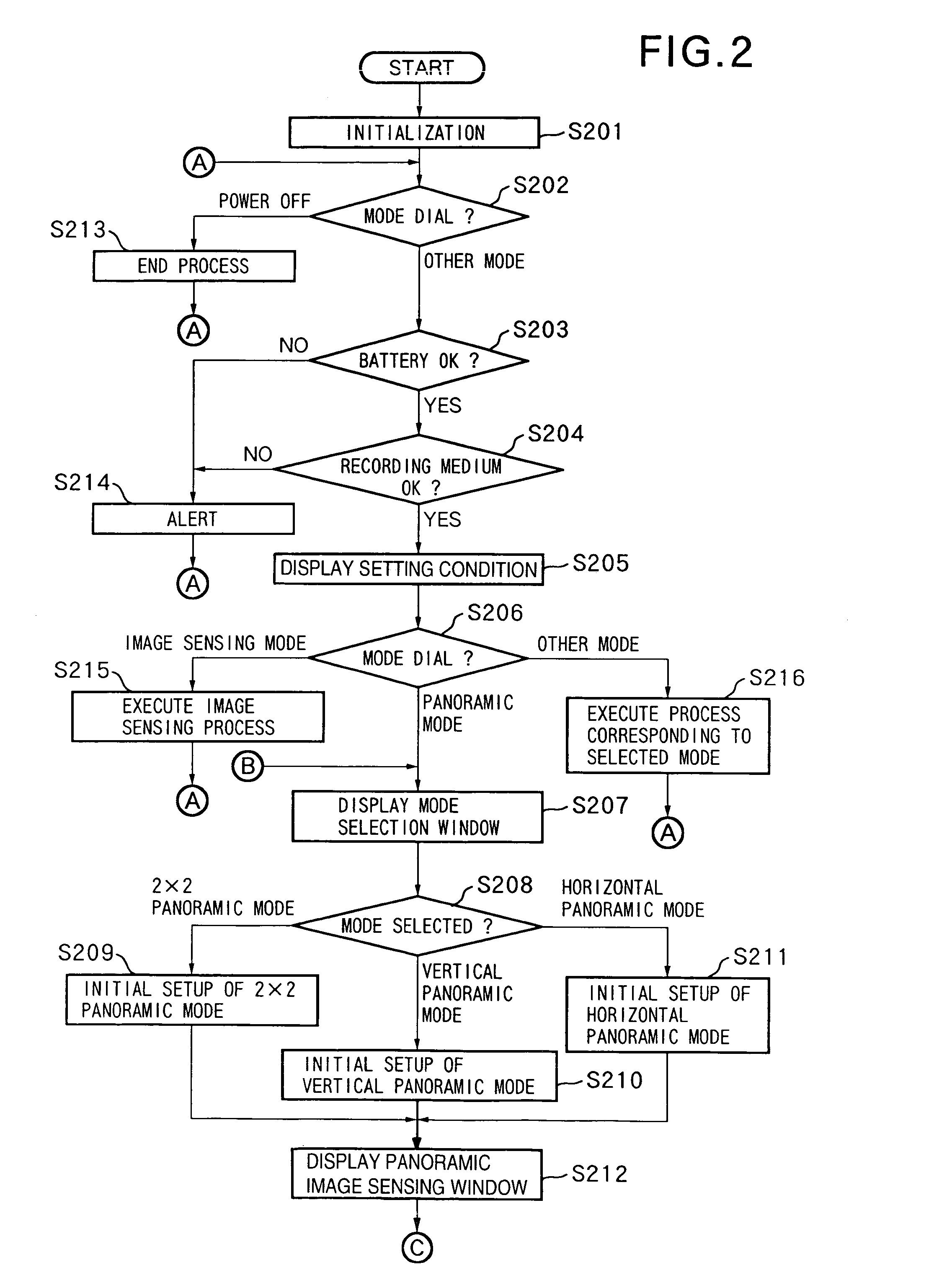
[0479]Upon power ON after battery exchange or the like, the system control circuit 50 initializes flags, control variables, and the like, and initializes the respective units of the image processing apparatus 400 (step S901).

[0480]The system control circuit 50 checks the setting position of the mode dial 60. If the mode dial 60 is set at a power OFF position (step S902), the system control circuit 50 executes a predetermined end process (step S903). More specifically, the system control c...


PUM


Abstract

This invention has as its object to provide a convenient image processing apparatus which does not limit image sensing purposes. To achieve this object, an image processing apparatus has a recording medium for recording and playing back an image sensed by an image sensing unit, and an image display unit for playing back and displaying at least an image sensed before the current image. The image display unit has a display layout mode for displaying the current image sensing signal and at least the image sensed before the current image sensing signal with their partial boundary regions overlapping each other.

Description

BACKGROUND OF THE INVENTION[0001]The present invention relates to an image processing method and apparatus for sensing, recording, and playing back still and moving images, a control method therefor, and a storage medium which stores a control program for controlling the image processing apparatus.[0002]Conventionally, image processing apparatuses such as electronic cameras and the like, which record / play back still and moving images using memory cards having solid state memory elements as recording media have already been commercially available, and electronic cameras with electronic viewfinders such as color liquid crystal panels and the like have also been commercially available.[0003]These electronic cameras allow the electronic camera user to determine the camera angle by continuously displaying images before sensing, and to confirm the sensed images by playing back and displaying them.[0004]Especially, the function of generating a panoramic image by combining a plurality of se...

Claims


Application Information

Patent Timeline
IPC IPC(8): H04N5/225H04N5/232
CPCH04N5/23293H04N23/632
Inventor YAMAGISHI, YOICHIYAMAGAMI, TAKU
Owner CANON KK
Why Eureka
Try Eureka