Reticle gripper barrier system for lithography use

a technology of lithography and gripper, which is applied in the field of lithography, can solve the problems of swamp critical dimension, lithographic tool damage, and reticle damage, and achieve the effect of greatly enhancing the quality of wafer images produced in the lithographic system

a technology of lithography and gripper, which is applied in the field of lithography, can solve the problems of swamp critical dimension, lithographic tool damage, and reticle damage, and achieve the effect of greatly enhancing the quality of wafer images produced in the lithographic system

US7136151B2Inactive Publication Date: 2006-11-14ASML HLDG NV

Image

  • Reticle gripper barrier system for lithography use
  • Reticle gripper barrier system for lithography use
  • Reticle gripper barrier system for lithography use

Examples


Embodiment Construction

[0031]While the present invention is described herein with reference to illustrative embodiments for particular applications, it should be understood that the invention is not limited thereto. Those skilled in the art with access to the teachings provided herein will recognize additional modifications, applications, and embodiments within the scope thereof and additional fields in which the invention would be of significant utility.

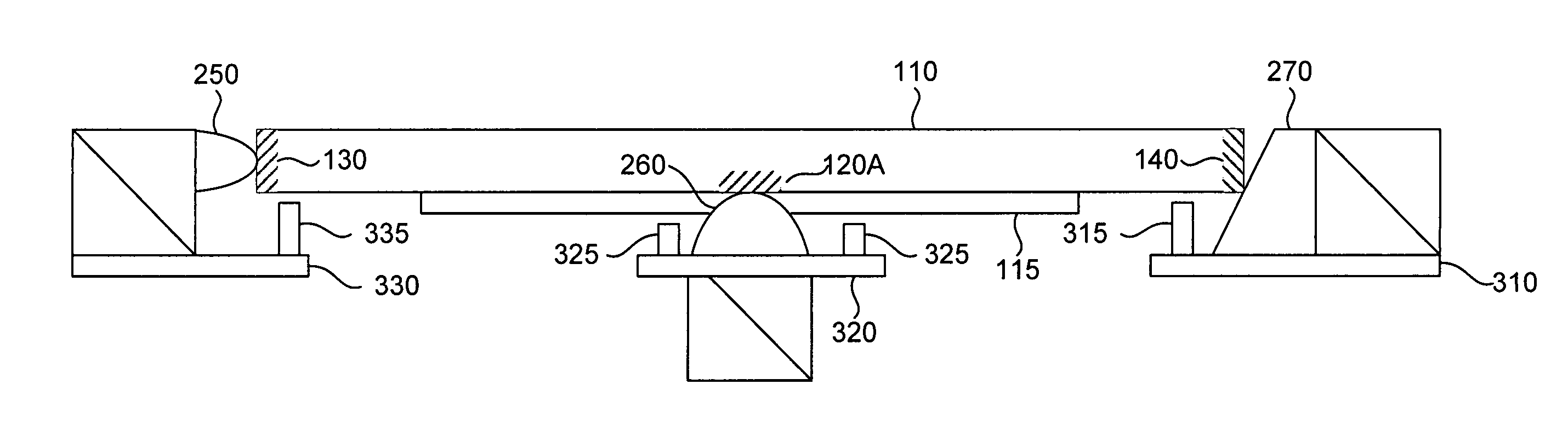
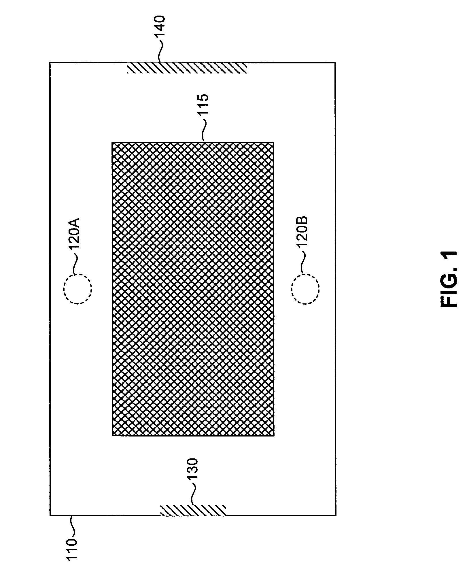
[0032]FIG. 1 is a diagram of a lithographic reticle having a mask. Such an arrangement is commonly used in lithographic applications. The system includes reticle 110; mask 115; and contact spots 120A, 120B, 130 and 140. Contact spots 120A, 120B, 130 and 140 indicate locations on the reticle in which reticle gripping surfaces will contact the reticle to secure it in place for use. These locations are shown for illustration purposes only, and can be located at other regions of reticle 110.

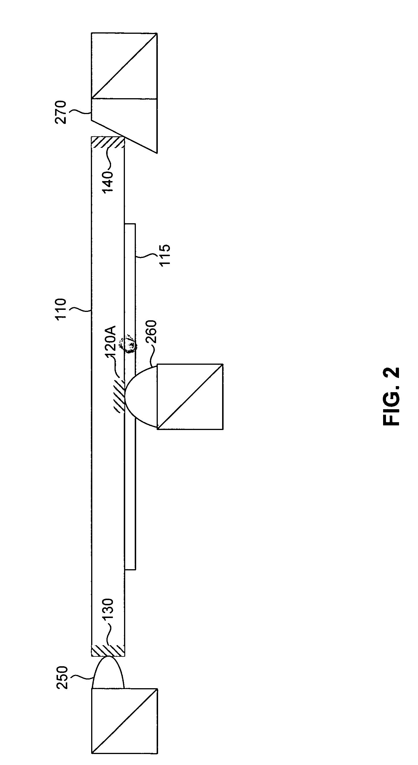
[0033]FIG. 2 is a diagram of lithographic reticle 110 with mask 115 h...


PUM

PropertyMeasurementUnit
angleaaaaaaaaaa
thickaaaaaaaaaa
heightaaaaaaaaaa

Abstract

A reticle gripper barrier system for use in concert with a reticle gripper device that contacts a lithographic reticle is presented. In a particular embodiment, a reticle gripper barrier device includes a support plate affixed near or to the reticle gripper device and a gripper barrier or a set of concentric gripper barriers affixed to or near the support plate. A reticle gripper barrier system includes one or more reticle gripper barrier devices that form a complete or partial barrier around the point or points where the reticle gripper device contacts a lithographic reticle. The gripper barriers block contaminants and prevent them from migrating towards the mask and do not contact the lithographic reticle. The gripper barriers can be interleaved with corresponding contact barriers on a lithographic reticle, which the gripper device is contacting.

Description

BACKGROUND OF THE INVENTION[0001]1. Field of the Invention[0002]The present invention relates to lithography, and more particularly, to reticle gripper devices used in lithography.[0003]2. Background of Invention[0004]Lithography is a process used to create features on the surface of substrates. Such substrates can include those used in the manufacture of flat panel displays, circuit boards, various integrated, circuits, and the like. A semiconductor wafer, for example, can be used as a substrate to fabricate an integrated circuit.[0005]During lithography, a reticle is used to transfer a desired pattern onto a substrate. The reticle is formed of a material transparent to the lithographic wavelength being used, for example, glass in the case of visible light. In other systems, such as extreme ultra violet (EUV) lithography systems, a reflective mask can be used that reflects the lithographic wavelength being used. The reticle has an image printed on it, referred to as a mask. The siz...

Claims


Application Information

Patent Timeline
14 Nov 2006
Publication
US7136151B2
IPC
G03B27/62; G03F9/00
CPC
G03F7/707; G03F7/70741
Inventors
LENOX, RICHARD; ROUX, STEPHEN