Magnetic recording and reproducing apparatus with recording layer having predetermined convex-concave pattern

a recording layer and convex pattern technology, applied in the direction of digital recording, maintaining head carrier alignment, instruments, etc., can solve the problems of servo signal degradation, head crash, and reached limit, so as to accelerate the thermal fluctuation of perpendicular magnetic recording medium. , the effect of reducing the thermal fluctuation

Inactive Publication Date: 2006-11-14
TDK CORPARATION
View PDF16 Cites 15 Cited by
  • Summary
  • Abstract
  • Description
  • Claims
  • Application Information

AI Technical Summary

Problems solved by technology

With respect to improving the track density, there have been raised problems of processing limitation about magnetic heads, side-fringe or crosstalk caused by expansion of magnetic fields of magnetic heads, and so forth, and therefore, it can be said that the improvement in areal recording density by progressing the track-density increasing technique for magnetic heads, which is merely an extension of the conventional improvement technique, has reached the limit.
However, there is a possibility that the convex-concave shape of the recording layer may impede the stable flying characteristic of a magnetic head and thus cause a problem of head crash or the like.
Once recorded, the servo signal is normally not recorded again by the magnetic head, and therefore, it is susceptible to the influence of thermal fluctuation over the long term so that there may arise a problem that the servo signal is degraded due to a reduction in recording magnetization, resulting in reduction of the tracking servo signal quality.
However, if the convex-concave shape of the magnetic layer is determined without taking a scheme into consideration, there may arise a problem that the servo signal output decreases in relation to the magnitude of the depth of the concave portion of the magnetic layer.
Therefore, with respect to servo tracking signals at the convex portions of the magnetic layer formed in the convex-concave pattern, it has been difficult to ensure a sufficient long-term reliability against thermal fluctuation.

Method used


Image

  • Magnetic recording and reproducing apparatus with recording layer having predetermined convex-concave pattern
  • Magnetic recording and reproducing apparatus with recording layer having predetermined convex-concave pattern
  • Magnetic recording and reproducing apparatus with recording layer having predetermined convex-concave pattern

Examples


Embodiment Construction

[0073]Hereinbelow, the invention of a first group and the invention of a second group will be described in order.

[0074]Description will be first given in detail about an embodiment of the invention of the first group (corresponding to FIGS. 1 to 8).

[0075][Description about the Invention of First Group]

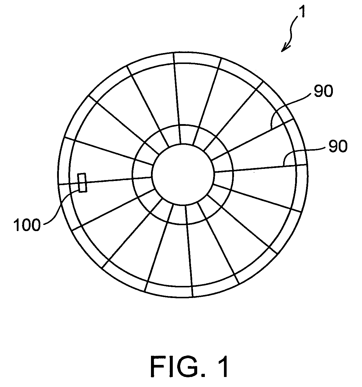
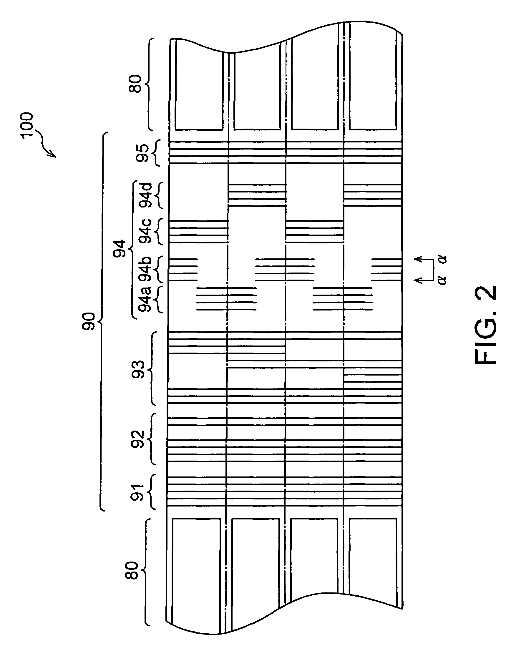
[0076]A magnetic recording and reproducing apparatus of the present invention comprises a magnetic recording medium having data information recording portions and servo information portions for tracking, and a magnetic head for detecting servo information of the servo information portions and recording and reproducing data information on and from the data information recording portions.

[0077]At the outset, an example of a schematic structure of the magnetic recording and reproducing apparatus will be described with reference to FIG. 6 in order to understand the overall structure of the apparatus.

[0078]Description of Example of Schematic Structure of Magnetic Recording and Reproducing A...


PUM

PropertyMeasurementUnit
thicknessaaaaaaaaaa
thicknessaaaaaaaaaa
thicknessaaaaaaaaaa

Abstract

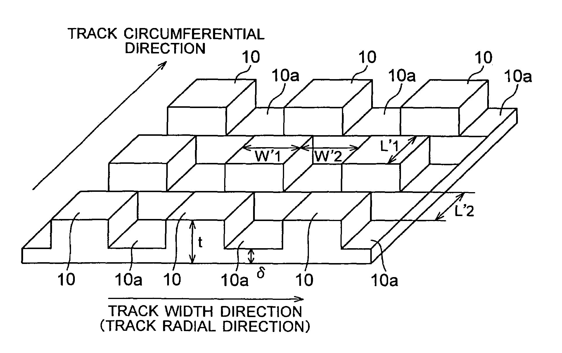
In the present invention, with respect to a convex-concave structure necessary for respective functions of a servo area in a perpendicular magnetic recording medium, a specification of configuration and magnetic property of a convex-concave magnetic layer of the perpendicular magnetic recording medium is set so as to overcome a demagnetizing field that accelerates thermal fluctuation. Therefore, in a magnetic recording and reproducing apparatus using the perpendicular magnetic recording medium having servo tracking signals at convex portions of the magnetic layer formed in a convex-concave pattern, it is possible to suppress degradation of the servo signals caused by the thermal fluctuation to thereby ensure a stable servo function over the long term.

Description

BACKGROUND OF THE INVENTION[0001]1. Field of the Invention[0002]The present invention relates to a magnetic recording and reproducing apparatus including a magnetic recording medium having a magnetic recording layer formed in a predetermined convex-concave pattern on a substrate and thus having so-called servo areas and information data areas (a magnetic recording medium of a discrete type) and a magnetic head for detecting servo signals on the magnetic recording medium and recording and reproducing information data on and from the medium.[0003]2. Description of the Related Art[0004]Improvement in areal recording density of magnetic recording mediums such as hard disks has conventionally been achieved by techniques of both (1) improving the linear recording density and (2) improving the track density. In order to achieve further and higher densification in future, it is necessary to improve the areal recording density based on the foregoing both techniques.[0005]With respect to impr...

Claims


Application Information

Patent Timeline
Patent Type & Authority Patents(United States)
IPC IPC(8): G11B5/62
CPCB82Y10/00G11B5/1278G11B5/743G11B5/82G11B5/855
Inventor TAGAMI, KATSUMICHI
Owner TDK CORPARATION
Why Eureka
Try Eureka