Magneto-optical recording device capable of setting the time phase of laser pulses and magnetic fields

a laser pulse and time phase technology, applied in the field of magnetic field modulationrecordingsystem magnetooptical recording method and apparatus for recording information, can solve the problems of signal quality deterioration, extremely deteriorated reproduction signal quality, and deterioration of reproduction signal quality

Inactive Publication Date: 2006-11-14
CANON KK
View PDF16 Cites 8 Cited by
  • Summary
  • Abstract
  • Description
  • Claims
  • Application Information

AI Technical Summary

Benefits of technology

[0015]The present invention has been made to solve the above problems and its object is to provide a magneto-optical recording method and apparatus for recording information in which, even when a recording power or medium temperature fluctuates, a sufficient phase margin can be secured to obtain a reproduction signal having a preferable quality.
[0019]a step of setting time phases of a laser pulse and a modulation magnetic field to a value of a time phase of maximizing a recording power margin in accordance with the evaluation result.
[0023]means for setting time phases of a laser pulse and a modulation magnetic field to a value of a time phase of maximizing a recording power margin in accordance with the evaluation result.

Problems solved by technology

During the temperature lowering, if an applied magnetic field expands to the switching region of a modulation magnetic field and a magnetic field is not applied at a sufficient intensity, the quality of a reproduction signal is extremely deteriorated.
At the same time, however, there is a problem that it is difficult to secure a sufficient phase margin and thereby, the quality of a reproduction signal is deteriorated.
When the above phase margin cannot be sufficiently secured, a phase shift exceeding the phase margin between a laser pulse and a modulation magnetic field may almost certainly occur due to a phase shift caused by the fluctuation of electrical components constituting an apparatus, a phase shift caused by the temperature characteristic of an electric system, or a phase shift caused due to environmental change such as temperature and thereby a signal quality is deteriorated.
However, the recording-power dependency or cross-write characteristic of a recording medium is not considered at all.
Therefore, a signal quality is deteriorated because the phase relation is changed due to the fluctuation of a medium temperature or change of recording powers.

Method used


Image

  • Magneto-optical recording device capable of setting the time phase of laser pulses and magnetic fields
  • Magneto-optical recording device capable of setting the time phase of laser pulses and magnetic fields
  • Magneto-optical recording device capable of setting the time phase of laser pulses and magnetic fields

Examples


first embodiment

(First Embodiment)

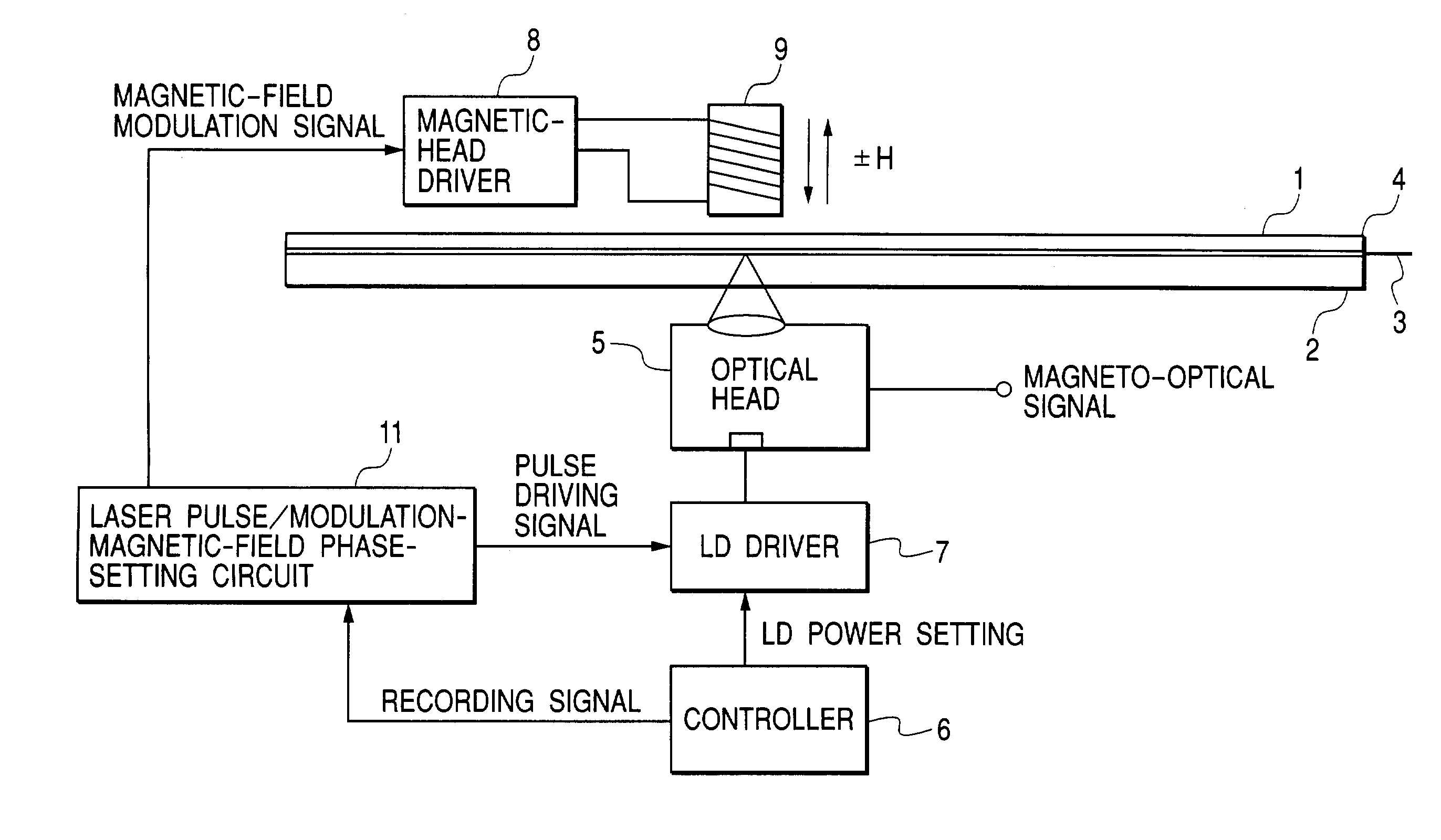
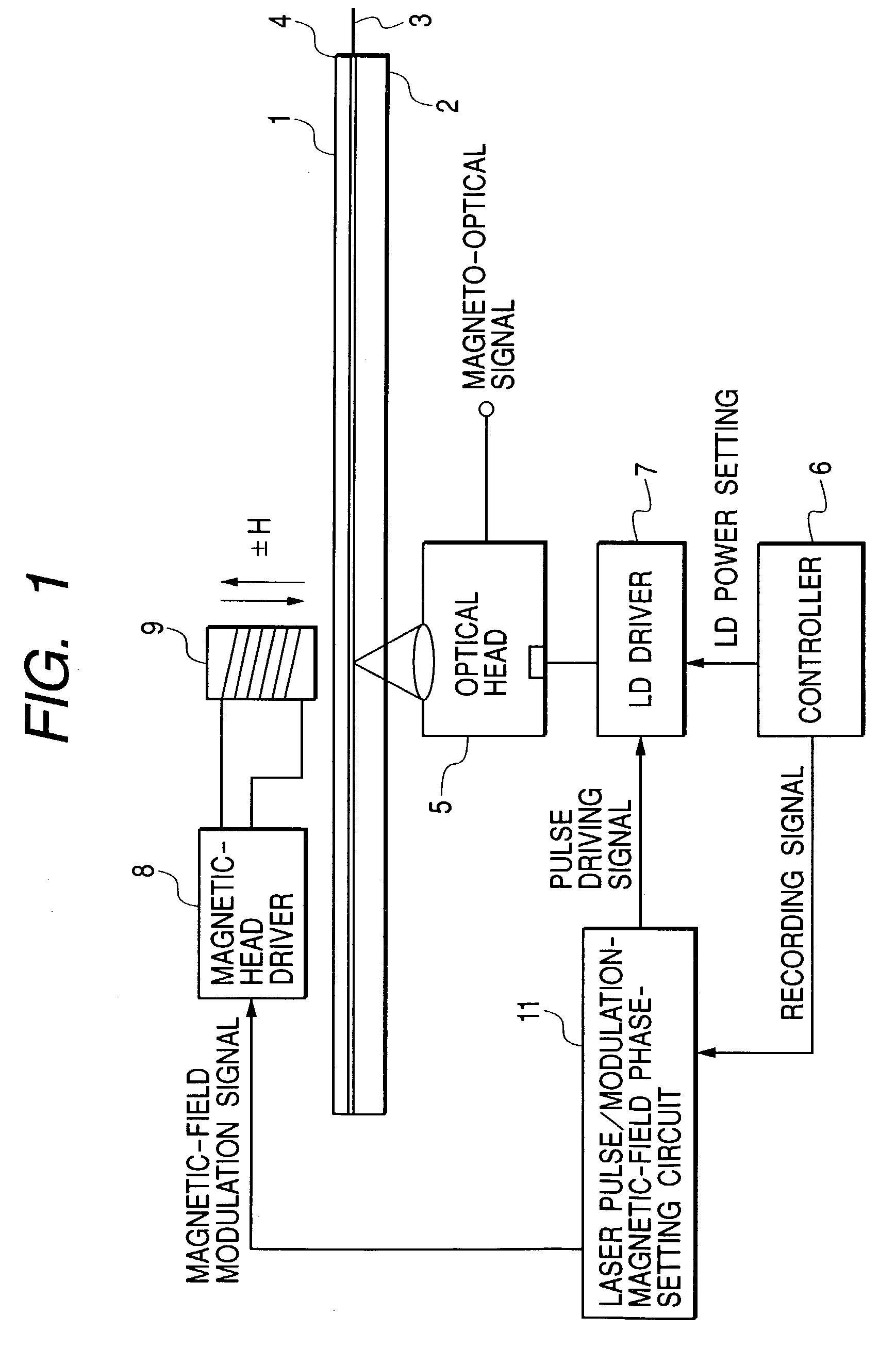
[0038]FIG. 1 shows a configuration of a magneto-optical recording apparatus of the present invention. In FIG. 1, reference numeral 1 denotes a magneto-optical disk obtained by adhering a magneto-optical recording medium 3 to a substrate 2 made of glass or plastic and moreover forming a protective film 4 on the medium 3. The magneto-optical disk 1 is supported by a spindle motor with a magnet chucking or the like so as to be rotatable about a rotational axis. Reference numeral 5 denotes schematically an optical head for irradiating the magneto-optical disk 1 with a laser beam and obtaining information from reflected light, which is constituted by a condenser lens (ex. NA:0.60), actuator for driving the condenser lens, semiconductor laser (ex. λ:650 nm), beam splitter, and polarization beam splitter. A laser beam emitted from the semiconductor laser is applied to the magneto-optical disk 1 through an optical-component group. In this case, the condenser lens is contro...

second embodiment

(Second Embodiment)

[0058]Because a configuration of a magneto-optical recoding apparatus used for the second embodiment is the same as that as shown in FIG. 1, the configuration is described by referring to FIG. 1.

[0059]In the case of this embodiment, a test signal is recorded in a dedicated recording-test region. However, the second embodiment is different from the first embodiment in that a test signal is also recorded in adjacent tracks. It is not always necessary to form a recording test region over the circumference of a disk. However, it is necessary that the region is formed over three or more tracks.

[0060]Hereafter, description is made along the flowchart shown in FIG. 8.

[0061]First, before actually performing recording, the phase Phase_I of a laser pulse and a modulation magnetic field is set by the laser-pulse / modulation-magnetic-field-phase setting circuit 10. (S00)

[0062]Though an initial set value is not restricted, when the phase relation is previously stored in a memor...

third embodiment

(Third Embodiment)

[0082]Because a configuration of a magneto-optical recording apparatus used for the third embodiment is the same as that in FIG. 1, the configuration is described by referring to FIG. 1.

[0083]In the case of this embodiment, a laser-pulse / modulation-magnetic-field setting sequence is simplified to shorten a test time by considering that the upper limit of a recording power margin is controlled by the cross write characteristic in the case of the second embodiment.

[0084]In the case of this embodiment, a test signal is recorded in a dedicated recording-test region. However, it is not always necessary to form the recording test region over the circumference of a disk.

[0085]Description is made below along the flowchart shown in FIG. 12.

[0086]First, before actually performing recording, the phase Phase_I of a laser pulse and a modulation magnetic phase is set to a laser-pulse / modulation-magnetic-field-phase setting circuit 10. (S00)

[0087]Though an initial set value is no...


PUM

PropertyMeasurementUnit
magnetic fieldaaaaaaaaaa
recording poweraaaaaaaaaa
timeaaaaaaaaaa

Abstract

The present invention provides a magneto-optical recording method capable of securing a sufficient phase margin, even if a recording power or medium temperature fluctuates, and obtaining a reproduction signal having a preferable quality, wherein the time phases of a laser pulse and a modulation magnetic field are set to a time phase of maximizing in which a recording power margin.

Description

BACKGROUND OF THE INVENTION[0001]1. Field of the Invention[0002]The present invention relates to the so-called pulse-assisted magnetic-field-modulation-recording-system magneto-optical recording method and apparatus for recording information by applying a modulation magnetic field corresponding to the information by a magnetic head while irradiating a magneto-optical recording medium with a laser beam emitted like a pulse.[0003]2. Related Background Art[0004]In the case of a magnetic-field-modulation magneto-optical recording apparatus, information is recorded in a magneto-optical disk by arranging an optical head and a magnetic head so as to interpose the magneto-optical disk between the heads and applying a magnetic field whose polarities are reversed in accordance with a recording signal generated by the magnetic head to the magneto-optical disk while irradiating the magneto-optical disk with a laser beam emitted from the optical head.[0005]The magnetic-field-modulation recording...

Claims


Application Information

Patent Timeline
Patent Type & Authority Patents(United States)
IPC IPC(8): G11B11/00G11B7/125G11B11/105G11B7/1267
CPCG11B7/1267G11B11/1051G11B11/1053G11B11/10595
Inventor MIYAOKA, YASUYUKI
Owner CANON KK
Why Eureka
Try Eureka